
iTechGuides is reader-supported. When you buy through links on our site, we may earn an affiliate commission. As an Amazon Associate I earn from qualifying purchases. Learn more
Yes. A nominal 12 V, 7 A resistive heater can normally be controlled efficiently with PWM using a logic-level N-channel MOSFET as a low-side switch. At its rated operating point it draws about 84 W, while the MOSFET switches the full approximately 7 A during each on-pulse. Use a fuse, correctly sized wiring, a gate pulldown, and an independent thermal cutoff where overheating could be hazardous.
What the electrical numbers mean
Assuming the heater really draws 7 A from a 12 V supply:
- Full-power load:
P = V × I = 12 × 7 = 84 W. - Approximate hot operating resistance:
R = V ÷ I ≈ 1.71 Ω. This is an operating-point estimate, not necessarily the cold resistance. - PWM current: during an on-pulse the heater still draws approximately 7 A; at 50% duty cycle it does not draw a continuous 3.5 A. Its average input power is approximately half of full power.
| PWM duty | Approximate average power |
|---|---|
| 0% | 0 W |
| 10% | 8.4 W |
| 25% | 21 W |
| 50% | 42 W |
| 75% | 63 W |
| 100% | 84 W |
Because thermal mass and heat loss are slow compared with the switching period, the heater responds mainly to average power. Temperature itself is not generally proportional to duty cycle: airflow, mounting, ambient temperature, thermal mass, and resistance change as the element heats.
Recommended low-side circuit
          +12 V supply
               |
             FUSE
               |
          Heater positive
          Heater negative
               |
            Drain Q1
PWM GPIO--100 ohm--Gate  (logic-level N-MOSFET)
            Source Q1
               |
              GND

Gate-to-source pulldown: 100 kOhm from Gate to GND
Controller GND connected to supply GND
Put the fuse close to the 12 V source so a downstream short is protected. Connect the heater to +12 V and switch its negative lead with the MOSFET. This topology keeps the MOSFET source and microcontroller ground at the same reference and avoids the high-side gate driver required by an N-channel MOSFET on the positive rail.
#1 Best Overall

- Working voltage: DC 5V-36V, the trigger source: digital high-low (DC 3.3V - 20V), continuous current: 15A, maximum current and power: 30A, 400W, operating Temperature: -40-85℃, size: 1.34x0.67x0.47inch/34 x 17 x12mm (length x width x height)
- DUAL MOS DRIVE: The MOSFET motor board Utilizes dual MOS parallel connection with active output, featuring lower internal resistance, higher current, and robust power output (15A, 400W at room temperature), meeting the requirements of most devices
- WIDE VOLTAGE RANGE, PWM SUPPORT: With a working voltage range of DC 5V to 36V and compatibility with PWM signals, this PWM regulator control panel offers versatility in controlling devices. It accepts digital signals within the voltage range of DC 3.3V to 20V, making it suitable for use with micro controller IO ports, PLC interfaces, and other DC power sources
- COMPACT DESIGN, EASY INTEGRATION: Measuring just in 34x17x12mm (1.34x0.67x0.47inch), this high power PWM MOSFET driver module offers a compact form factor, facilitating effortless integration into various applications. Easily achieve control over high-power devices with this versatile and efficient module
- WIDELY APPLICATIONS: The MOSFET switch drive module is a versatile power control module that excels in a wide range of applications. Its design allows for precise control of high-power devices such as motors, LED lights, bulbs, micro-pumps, and solenoid valves. By accepting PWM signals, it can accurately regulate motor speeds, adjust lamp brightness, and more
A practical starting point is a 47–220 Ω series gate resistor and a 47–100 kΩ gate-to-source pulldown. The resistor limits GPIO peak current and ringing; the pulldown keeps the heater off while the controller is disconnected, booting, or in reset.
Selecting the MOSFET
Use guaranteed on-resistance at your gate voltage
Choose an N-channel power MOSFET whose maximum RDS(on) is specified at the voltage your controller can actually provide. A 5 V controller should use a part characterized at 4.5 or 5 V; a 3.3 V controller needs a part specified at 2.5 or 3.3 V, or a gate driver. VGS(th) only indicates the start of conduction at a small test current and is not a full-turn-on specification. See the discussion of gate plateau behavior from TI at TI.
Allow voltage, current, and thermal margin
- For a clean regulated bench supply, 30 V may be workable; automotive or long-cable systems generally deserve a 40–60 V device plus transient protection.
- Use continuous-current capability comfortably above 7 A, but do not treat the headline current number as the design limit. It often assumes a 25 °C case and ideal cooling.
- Check gate charge, package thermal resistance, PCB copper, enclosure temperature, and safe operating area. Infineon explains how to interpret SOA curves at Infineon.
Example parts and their limitations
| Part | Relevant information | Use with care |
|---|---|---|
| onsemi NTMFS5C628NL | 60 V N-channel, 3.3 mΩ maximum at 4.5 V, 5 × 6 mm surface-mount package. Datasheet | Low conduction loss is attractive, but it needs a properly designed copper area; its advertised 150 A is not a casual-PCB rating. |
| Infineon IRLB8721 | 30 V, TO-220, 16 mΩ maximum at 4.5 V, familiar 7.6 nC typical gate charge. Product page | Infineon marks it end of life/discontinued, so treat it as a legacy reference or use only with verified authorized stock and a qualified replacement. |
Do not default to an “IRF520 module” or another part merely because it says logic level. Verify its on-resistance at 3.3 or 5 V and its actual thermal path.
Recommended Free Tools
Rank #2

- High Current Dual MOSFET: Dual MOSFET design delivers up to 15 A continuous and 30 A peak at 400 W; strong drive for DC loads; ideal as a dc motor speed controller for robots, pumps, fans
- Wide Voltage and PWM Control: Accepts DC 5-36 V and logic 3.3-20 V; supports 0-20 kHz PWM for smooth ramping and precise speed or dimming; use as a pwm controller or motor controller in labs and builds
- Compact DIY-Friendly Board: About 1.34 x 0.67 x 0.47 in; small mosfet kit fits tight enclosures; simple two wire input and output layout integrates with microcontroller pins and breadboards
- Versatile Applications: Adjust DC motor speed, LED brightness and bulb dimming; drive micro pumps and solenoids; clean PWM input supports stable response and low heat for longer component life
- Rugged Reliability: Operates from minus 40 to 85 °C; dual MOSFET layout resists voltage spikes and load surges; dependable motor driver for industrial, automotive and DIY use
Estimate MOSFET heating
For a fully enhanced MOSFET, conduction loss is approximately PMOSFET = I² × RDS(on). At 7 A:
- 16 mΩ gives about 0.78 W and a voltage drop of about 0.112 V.
- 3.3 mΩ gives about 0.16 W and a voltage drop of about 0.023 V.
Use the datasheet’s maximum resistance at the real gate voltage and account for its increase with junction temperature. Add switching loss, PCB resistance, connector resistance, and wiring loss. Even less than 1 W can require substantial copper or a heatsink in a sealed, hot enclosure.
Power supply, fuse, and wiring
Choose a supply rated for at least 7 A continuously, with margin for cold-start behavior, other loads, cable loss, and derating. Measure cold resistance and startup current instead of assuming the label describes every condition. Wire, connectors, switches, fuse holder, and PCB traces must all be rated for the current; solderless breadboards and small barrel connectors are poor choices for a continuous 7 A load.
Rank #3
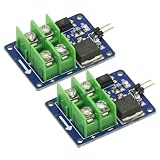
- 2PCS 3V 5V Low Voltage Control High Voltage 12V 24V 36V switch Mosfet Module,MOSFET Switching Module for Arduino Connect IO MCU PWM Control Motor Speed 22A
- Input control voltage :3.3V-12V
- Output charged voltage: 5-36V
- Board use of opto isolated, completely separated from the 2-terminal voltage.
- Input is controlled by a 2 pin control ,a ground control can be directly connected to the control switch.
There is no universally correct fuse value. Select it from normal current, startup surge, wire ampacity, fuse time-current curve, nuisance-trip tolerance, and acceptable fault energy. A fuse protects the wiring; it does not replace MOSFET thermal design.
The Tool Desk
Outbyte Driver Updater FREEScan for outdated or missing drivers - takes under a minuteDriver Scan →Outbyte PC Repair FREERepair Windows errors before they cause bigger problemsFix Now →For automotive or long-wire installations, a TVS or other transient suppressor may be appropriate. Select its standoff and clamp voltage for the actual 12 V rail rather than placing an arbitrary TVS across a regulated supply. Add bulk capacitance near the power entry and suitable decoupling near the controller or driver.
PWM frequency and gate drive
Start around 100–1,000 Hz for most thermal loads. Lower rates can work when visible or audible pulsing is unimportant; higher rates may reduce audible artifacts but increase gate-charge loss and EMI. Validate the chosen rate by observing MOSFET temperature, supply ripple, electromagnetic interference, and heater response.
Rank #4

- MOSFET Switch Drive Module:for control motor speed light bulbs LED lights DC motors micro-pumps solenoid valves etc
- Size:34*17*12mm
- Voltage:DC 5-36V 15A Max:30A
- Operating temperature:-40-85℃
- Commodities include:6Pcs Trigger Switch Driver Module;6Pcs Heat Sink;1Pcs Screwdriver;10Pcs Male and Female Lines;10Pcs Male and Male Lines
A GPIO can often drive one modest-gate-charge MOSFET directly at these frequencies. Use a dedicated driver when gate charge is high, wiring is long, several MOSFETs are used, switching is fast, or a 3.3 V output cannot charge the gate decisively. TI’s LMG1020-Q1 datasheet illustrates the sort of driver used when stronger transitions are needed.
When a flyback diode is unnecessary
A genuinely resistive heater, nichrome element, or resistive pad does not store substantial magnetic energy, so it normally needs no flyback diode. Motors, solenoids, relays, fans, transformers, and loads containing switching converters are different. Investigate the assembly before copying motor-driver protection; guidance on this distinction is available from Leobot.
A Peltier module is also not simply a resistor. One MOSFET can PWM one fixed heating direction, but heating and cooling require polarity reversal through an H-bridge or equivalent circuit.
Best Value

- 【Motor Speed Controller】Ultra-low voltage dc motor governor with the chip model: NE555; Potentiometer with switch function; Use a 2A resettable fuse to protect the controller; Power-on indicator. This controller can continuous change device working current and completely cut off.
- 【High Performance】Input supply voltage DC 1.8V-12V. Maximum continuous output current 2A. Maximum output power 30W. Duty cycle adjustable 0%-100%.
- 【Secure Enough】The speed controller is equipped with a self-recovery fuse. When the current is too large, the fuse is automatically disconnected. After cooling, the fuse is automatically restored.
- 【Pay Attention】①Please connect this DC controller to DC power supply. Never connect directly to household 220V AC power supply, or it will be damaged; ②Don't power supply larger than 15V. ③This is a 2A high current governor, which can't drive larger than 0.5A continuous current / the 775 motor / children's car motor. Please confirm again before purchasing.
- 【Widely Applications】It is suitable for the speed regulation of DC motor, fan, fish tank oxygen pump and other products in DC1.8V--12V.
Microcontroller setup
Use the board’s PWM facility, but check its actual pin, timer, resolution, default frequency, output voltage, GPIO-current limits, and boot behavior; Arduino-compatible boards are not identical.
initialize PWM output
set PWM duty to 0 during startup
validate the temperature sensor
if the sensor is invalid:
    disable the heater
else if temperature >= safety limit:
    disable the heater
else:
    calculate a duty command
    constrain duty to 0–100%
    output PWM duty
Ensure the controller ground and power ground have an intentional common reference. An isolated supply requires an appropriate signal-ground or isolated gate-drive arrangement.
Temperature regulation and independent safety
PWM duty is an open-loop power command, not a temperature setting. For regulation, place a suitable sensor at the surface or object whose temperature matters. Begin with hysteresis: turn heating on below a lower threshold and off above an upper threshold. PID can reduce variation after sensor placement, thermal lag, and limits are understood.
Quick wins for a faster PC:
Repair Windows errors before they cause bigger problemsFix Now →Scan for outdated or missing drivers - takes under a minuteDriver Scan →Clear out junk files and repair common Windows errorsFree Scan →- Reject disconnected, shorted, or implausible sensor readings.
- Set a hard maximum temperature and maximum duty.
- Define startup ramping, overtemperature shutdown, and restart behavior.
- Use an independent thermal fuse or thermostat where overheating could injure people, damage equipment, or start a fire. Firmware alone is not an adequate safety device.
For electronic current limiting, controlled startup, or resettable short-circuit protection, devices such as ST STEF12 or Analog Devices MAX15090B may be relevant, but they add complexity and must be checked for their exact current, thermal, and PWM behavior.
Quick Recap
Troubleshooting
| Symptom | Likely causes and checks |
|---|---|
| Heater always on | Floating gate, incorrect MOSFET pinout, shorted MOSFET, or firmware enabling the pin during boot. Confirm the pulldown and source reference. |
| MOSFET gets hot | Insufficient gate voltage, excessive on-resistance, slow edges, high PWM frequency, inadequate copper, or poor heatsinking. |
| Heater is weak | Supply sag, undersized wiring, connector loss, MOSFET not fully enhanced, wrong pinout, or missing common ground. |
| Controller resets | Supply noise or ground drop. Improve wiring, grounding, bulk capacitance, and decoupling; check the MOSFET switching waveform. |
| Fuse opens immediately | Short circuit, wiring error, excessive startup current, or a fuse not coordinated with the wire and load. |
| PWM has no effect | Wrong timer or pin, PWM not initialized, gate not referenced to source, or a failed MOSFET. |
| Temperature overshoots | Open-loop operation, poorly placed sensor, excessive thermal lag, or too much duty before feedback responds. |
Alternatives and design trade-offs
- Low-side N-channel: simplest and most efficient for a ground-referenced controller.
- High-side switching: preserves heater ground but needs a P-channel device or high-side driver; a GPIO cannot directly drive a high-side N-channel gate to 12 V.
- PWM: keeps MOSFET dissipation low but can create EMI and ripple.
- Linear control: usually unsuitable because the MOSFET would dissipate a large fraction of the heater’s 84 W and must be designed for linear SOA.
- Relay: suitable for slow hysteresis on/off control, not rapid PWM; contacts wear and switching speed is limited.
Product prices and availability are accurate as of the date/time indicated and are subject to change. Any price and availability information displayed on Amazon at the time of purchase will apply.

