
The Tool Desk
Outbyte Driver Updater FREEFix the driver behind crashes, sound loss and screen glitchesFind Drivers →Outbyte PC Repair FREEClear out junk files and repair common Windows errorsFree Scan →iTechGuides is reader-supported. When you buy through links on our site, we may earn an affiliate commission. As an Amazon Associate I earn from qualifying purchases. Learn more
To bring up Wi-Fi on the Ultra96-V2, build a PetaLinux 2019.2 image that includes the board’s ATWILC3000 driver, matching firmware, Wi-Fi utilities and the Ultra96-specific power-sequencing patch. Then install the image on a microSD card, boot the board and verify that Linux creates wlan0. The board can act as an access point at 192.168.2.1 or join an external Wi-Fi network; after it joins, connect to its newly assigned IP address instead.
What you need before starting
This procedure follows Whitney Knitter’s Ultra96-V2 bring-up project for Vivado and PetaLinux 2019.2, published in 2020. The board has an integrated Microchip ATWILC300-MR110CA Wi-Fi/Bluetooth module; it is not a USB Wi-Fi adapter. The Ultra96-V2 Hardware User’s Guide (2020) specifies 802.11b/g/n Wi-Fi and Bluetooth 4.0.
- An Ultra96-V2 board, microSD card, 12 V power supply and a computer with Vivado and PetaLinux 2019.2 installed.
- A UART console connection for boot messages and login. The Hackster project describes the AES-ACC-U96-JTAG pod as an option; UART/JTAG can also be connected manually.
- The project’s Vivado TCL script, Avnet PWM IP repository, board constraints and PetaLinux support files, including the
wilc3000-fwandultra96-miscrecipe directories.
The project targets PetaLinux 2019.2 specifically. Do not assume that the same BSP, recipes or kernel patch will work unchanged with a newer release. Avnet’s current board page says the Ultra96 family is no longer in production, which may affect board availability.
How the Ultra96-V2 Wi-Fi hardware is connected
The ATWILC300-MR110CA combo module connects to the MPSoC over Secure Digital interface SD1. The hardware guide identifies WLAN_IRQ as PS MIO76 and RADIO_EN as PS MIO7, and documents a yellow LED indicating Wi-Fi enable status. Because the radio depends on board-specific connections and power sequencing, adding a generic Linux Wi-Fi package alone is not sufficient.
#1 Best Overall

- Designed for students and beginners looking to understand Digital Logic, fundamentals of FPGAs
- Features the Xilinx Artix 7 FPGA compatible with Vivado Design Suite WebPACK Edition (free download available from Xilinx)
- On board user interfaces include 16 user switches, 16 LEDs, 5 user pushbuttons, and a
- Expansion opportunities with four Pmod ports including 3 standard 12-pin Pmod ports and 1 dual
- Does NOT ship with micro USB cable
Build and export the Vivado hardware design
First create the hardware platform that PetaLinux will use. In the 2019.2 project flow, add the Avnet PWM IP repository before sourcing the project TCL script. Validate and save the block design, create its HDL wrapper, import the board constraints, then run synthesis and implementation and generate the bitstream.
- In Vivado, add the Avnet PWM IP repository to the project’s IP repositories.
- Source the Ultra96-V2 project TCL script to create the block design.
- Validate and save the block design, then create the HDL wrapper.
- Import the board constraints; run synthesis and implementation; generate the bitstream.
- Export the hardware platform as an XSA and select Include bitstream. PetaLinux consumes this XSA, so export it before configuring the Linux project.
Create the PetaLinux project from the XSA
Source the PetaLinux 2019.2 settings script in your shell, then create a ZynqMP project and import the exported XSA. Replace the placeholders with your project name and the actual XSA location:
Rank #2

- Digilent Basys 3 Artix-7 FPGA Trainer Board: Recommended for Introductory Users
petalinux-create --type project --template zynqMP --name <PROJECT NAME>
petalinux-config --get-hw-description /<location of XSA file>
In the hardware configuration editor, change the serial port from PS UART0 to PS UART1 at Subsystem AUTO Hardware Settings > Serial Settings. This is the serial setting used by the project’s board bring-up flow.
Recommended Free Tools
Add the WILC driver, firmware and board support
The radio needs a coordinated set of kernel, firmware and root-filesystem components. In the project’s project-spec/meta-user/recipes-bsp area, add the project’s wilc3000-fw and ultra96-misc recipe directories. The custom wilc module recipe points to Avnet’s WILC3000 driver source; the separate firmware recipe supplies ATWILC3000 firmware.
Rank #3

- The best way to get started with FPGAs: Using a simple board with projects that build on eachother, now anyone can get started with FPGA development!
- Fun peripherals available: With 4 LEDs, 4 push-buttons, 7-segment display, USB connector, a VGA connector, and a PMOD (for expansion) you can have dozens of fun projects available to you out of the box!
- Works with Verilog and VHDL: No matter which programming language you want to get started with, the Go Board will work for you!
- No extra device required: Simply plug the Go Board into a USB port and go! Getting started with FPGAs has never been easier.
- Works with all operating systems: Windows, Mac, Linux
- Add
bsp.cfgandfix_u96v2_pwrseq_simple.patchto thelinux-xlnxrecipe and append them throughlinux-xlnx_%.bbappend. The patch addresses the power-up sequence required by the Ultra96-V2 ATWILC3000. - Enable the documented kernel settings, including
CONFIG_CMA_SIZE_MBYTES=1024,CONFIG_EDAC_CORTEX_ARM64=y,CONFIG_XILINX_APF=yandCONFIG_XILINX_DMA_APF=y. - Create and enable the custom
led-brightnessandwilcmodules. - In the root-filesystem configuration, include
iw,wpa-supplicant,wilc3000-fw,wilc, Bluetooth/BlueZ and the Ultra96 wireless support recipes. - Set
PREFERRED_VERSION_wilc-firmware = "15.2", appendbluez5 dbus, and remove the stockultra96-ap-setupimage package as in the project configuration.
These pieces are interdependent: the driver needs the firmware to initialize the radio, and the board-specific patch handles power sequencing. A successful build that omits one of them does not establish that Wi-Fi will work.
Build the image and prepare the microSD card
Build the configured project with:
petalinux-buildFor this PetaLinux 2019.2 flow, prepare a FAT32 boot partition and an EXT4 root-filesystem partition. Knitter’s 2020 project write-up, citing UG1144, reports at least 500 MB for the FAT32 partition and 4 MB of free space ahead of that partition. These are the project’s stated layout requirements, not a general specification for every PetaLinux version.
Rank #4
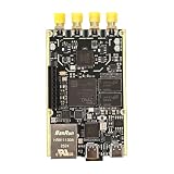
- 1. Product Name: 7020+AD9361 Version. with RFID code AD9361BBCZ
- 2. Petite appearance: The size is approximately 50 * 80mm, compact and lightweight, easy to carry. A small body shape indeed has powerful performance!
- 3. Introduce the local oscillator input interface and reference clock input interface;
- 4. RFIC CLOCK: 0.5ppm TCXO/FPGA/PEX(Default TCxO)
- 5. Supports multiple power supply modes: USB/JTAG/Pin header can all be powered
Package the boot files with the project’s FSBL, bitstream and PMU firmware:
petalinux-package --boot --fsbl ./images/linux/zynqmp_fsbl.elf --fpga ./images/linux/system.bit --pmufw ./images/linux/pmufw.elf --u-bootCopy BOOT.BIN, image.ub and system.dtb to the FAT32 partition. Extract rootfs.tar.gz onto the EXT4 partition.
Best Value

- Arty A7 comes in two FPGA variants: Arty A7-35T features Xilinx XC7A35TICSG324-1L. Arty A7-100T features the larger Xilinx XC7A100TCSG324-1.
- Internal clock speeds exceeding 450MHz, On-chip analog-to-digital converter (XADC), Programmable over JTAG and Quad-SPI Flash
- 256MB DDR3L with a 16-bit bus @ 667MHz, 16MB Quad-SPI Flash, USB-JTAG Programming circuitry, Powered from USB or any 7V-15V source
- 10/100 Mbps Ethernet, USB-UART Bridge
- 4 Switches, 4 Buttons, 1 Reset Button, 4 LEDs, 4 RGB LEDs, 4 Pmod connectors, shield connector
Boot the Ultra96-V2 from microSD
- Set SW3 switch 1 to off and switch 2 to on to select SD boot.
- Insert the prepared microSD card, connect the UART console, and attach the 12 V supply.
- Press the board’s power button and watch the UART output through startup and login.
Verify Wi-Fi and choose access-point or client mode
After logging in, run ifconfig. Confirm that the system lists wlan0; this is the basic interface check documented by the project.
| Mode | What to do | Address to use |
|---|---|---|
| Ultra96-V2 access point | Connect a computer to the board’s advertised access point. | Open 192.168.2.1 to reach the Ultra96 access-point page. |
| External Wi-Fi client | Open Wi-Fi Setup under Board Configuration and join the external network. | The original 192.168.2.1 address stops responding after association. Run ifconfig again and use the router-assigned IP address from a computer on the same network. |
Troubleshoot a missing wlan0
wlan0does not appear: Check that the image includes both thewilcdriver andwilc3000-fwfirmware, and that the custom modules were enabled. Confirm that the XSA came from the intended Ultra96-V2 design.- The radio does not initialize despite the driver being present: Verify that
fix_u96v2_pwrseq_simple.patchwas added through thelinux-xlnx_%.bbappendand included in the build. This board-specific power-sequencing change is required by the documented setup. - The board boots but serial interaction is not as expected: Check that PetaLinux hardware settings use PS UART1 rather than PS UART0, as specified in the project flow.
- The access-point page no longer opens after joining a router: That is expected in client mode. Use
ifconfigto find the newly assigned IP and access the board from a computer on the same network.
The cited project documents interface initialization and connectivity steps, not controlled throughput measurements. It does not establish a Wi-Fi speed or range figure for the Ultra96-V2.
Quick Recap
Product prices and availability are accurate as of the date/time indicated and are subject to change. Any price and availability information displayed on Amazon at the time of purchase will apply.

