
iTechGuides is reader-supported. When you buy through links on our site, we may earn an affiliate commission. As an Amazon Associate I earn from qualifying purchases. Learn more
Choose the HMC8193 for RF and LO frequencies from 2.5 to 8.5 GHz; choose the HMC8191 for 6 to 26.5 GHz or an IF extending to 5 GHz. Both are passive I/Q mixer MMICs, and both need an external 90° hybrid for the usual image-reject downconversion or single-sideband upconversion setup. The hybrid, its 50 Ω termination, and the complete signal path determine whether the desired sideband is selected and how much image rejection the assembled design achieves.
HMC8191 vs. HMC8193: the key specifications
The headline values below are typical data-sheet figures, not guaranteed performance across every frequency or operating condition. The two devices’ specifications are measured under different conditions, so treat the table as a selection guide rather than a controlled head-to-head test. Consult the individual data sheets for the conditions and frequency-specific curves relevant to your design: HMC8191 Rev. C data sheet and HMC8193 Rev. B data sheet.
| Parameter | HMC8193 | HMC8191 |
|---|---|---|
| RF and LO frequency range | 2.5–8.5 GHz | 6–26.5 GHz |
| IF range | DC–4 GHz | DC–5 GHz |
| Typical conversion loss | 9 dB, downconversion | 9 dB |
| Typical image rejection | 25 dBc | 25 dBc |
| Typical SSB noise figure | 15 dB | 9 dB |
| Typical downconverter input IP3 | 20 dBm | 24 dBm |
| Typical downconverter input P1dB | 13 dBm | 15 dBm |
| Typical input IP2 | 58 dBm | 55 dBm |
| RF-to-IF isolation | 22 dB | 20 dB |
| LO-to-RF isolation | 48 dB | 40 dB |
| LO-to-IF isolation | 38 dB | 40 dB |
| Typical amplitude balance | ±0.5 dB | ±0.5 dB |
| Typical downconverter phase balance | ±5° | ±5° |
| RF / LO / IF return loss | 13 / 13 / 18 dB | 15 / 15 / 15 dB |
| Package and operating temperature | 4 mm × 4 mm, 24-terminal ceramic LCC; −40°C to +85°C | 4 mm × 4 mm, 24-terminal ceramic LCC; −40°C to +85°C |
What these I/Q mixers do
Each part is a passive GaAs MESFET MMIC mixer with two mixer paths and integrated quadrature circuitry. The device has single-ended RF, LO, IF1, and IF2 connections. It can serve as an image-reject downconverter in a receiver or as a single-sideband (SSB) upconverter in a transmitter. It does not, by itself, provide a complete selected-sideband system: an external 90° hybrid and correctly balanced surrounding circuitry are part of the normal application.
“Passive” means the mixer does not need a conventional DC supply for ordinary operation; it does not mean the complete setup needs no power. The LO source, any LO amplifier, and other signal-chain components may require power. Nor should the IF ports be connected to arbitrary DC-biased circuitry without checking the data-sheet guidance.
#1 Best Overall

- Passive Mixer Frequency Range: Passive Mixer supports 0.5 to 500 MHz (ADE-1), 0.05 to 250 MHz (ADE-6), and 5 to 2500 MHz (ADE-25) bands, enabling precise RF signal translation across VHF/UHF systems for broadcast and communications use
- Low Conversion Loss Performance: Passive Mixer delivers 5.0 dB loss (ADE-1), 4.6 dB (ADE-6), and 7.0 dB (ADE-25), minimizing signal degradation during frequency translation in sensitive receiver front-ends
- RF Power Handling Capacity: Passive Mixer accepts up to 50 mW RF input power and supports 40 mA IF current, ensuring stable operation under typical VHF/UHF signal chain loading conditions
- Compact Form Factor Design: Passive Mixer features a lightweight miniaturized housing with standardized footprint, facilitating integration into space-constrained RF modules and portable test equipment
- VHF UHF Application Focus: Passive Mixer is engineered specifically for VHF and UHF frequency conversion tasks, including signal monitoring, spectrum analysis, and transceiver subsystems in field-deployable hardware
Which mixer should you choose?
Choose the HMC8193 for 2.5–8.5 GHz
- Its RF and LO range starts at 2.5 GHz, below the HMC8191’s 6 GHz lower limit.
- Its IF range is DC–4 GHz.
- It is a candidate for direct-conversion receivers, radar front ends, instrumentation, and SSB transmitters operating within its band.
- Its published typical figures include 15 dB SSB noise figure, 20 dBm downconverter input IP3, and 13 dBm downconverter input P1dB.
Choose the HMC8191 for 6–26.5 GHz
- It covers microwave frequencies above the HMC8193’s 8.5 GHz upper limit.
- Its IF range extends to 5 GHz.
- Its published typical figures include 9 dB SSB noise figure, 24 dBm downconverter input IP3, and 15 dBm downconverter input P1dB.
- It may suit test and measurement, aerospace or defense work, and point-to-point microwave radio when the frequency plan and measured performance fit.
For the 6–8.5 GHz overlap
Both parts cover this range. Decide using the IF requirement, the exact-frequency performance curves, noise and linearity budgets, isolation needs, evaluation hardware, and the external hybrid and layout required. The headline figures favor the HMC8191 for typical SSB noise figure and downconverter IP3/P1dB, while the HMC8193 lists higher typical LO-to-RF isolation. Those figures alone do not establish which will perform better in a particular assembled design.
Why the external 90° hybrid matters
For the standard image-reject or SSB configuration, Analog Devices specifies an external 90° hybrid for both parts. The mixer supplies two paths with a nominal 90° relationship; the external hybrid combines or splits the IF1 and IF2 signals so they add at one output and cancel at the other. Changing the phase assignment selects the opposite sideband. The unused sum or difference output must be terminated in 50 Ω, as shown in the HMC8191 and HMC8193 application circuits.
Rank #2
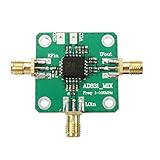
- RF input: 0.1-500MHz
- RF input: + 10dBm (1dB compression point)
- Local oscillator input: 0.1-500MHz
- Local oscillator input: -10dBm
- IF output: 0.1-200MHz
In upconversion, the IF signals feed the hybrid and its sum port is used as the input; the opposite hybrid output is terminated. The data sheets show opposite IF-to-hybrid orientations for upper- and lower-sideband operation. In downconversion, the RF enters the mixer and the desired IF is taken from the appropriate hybrid output. Which phase assignment produces the wanted sideband depends on whether the LO is above or below the RF.
What’s actually slowing this PC down?
Pick the symptom - the matching free tool is one click away.
Hybrid manufacturers may use different port and phase conventions. Confirm the wiring against the particular hybrid’s documentation, then verify the selected and rejected sidebands with a spectrum analyzer. A typical 25 dBc image-rejection figure is not a promise for every board: hybrid imbalance, IF-path amplitude or phase mismatch, PCB asymmetry, connectors, cables, temperature, and source or load mismatch all affect the result.
Rank #3

- [Enhanced Performance] With no shielding or isolation issues, this mixer improves system performance and reduces overall costs compared to passive mixers.
- [Low Dc Offset Characteristics] The amplifier's low dc offset characteristics make it ideal for dc, baseband frequency conversion and quadrature amplitude demodulation.
- [ Functionality] Boasting a +24 dbm third, order intermodulation point, it achieves -10 dbm lo power without requiring a high power lo drive.
- [Easy to Use Design] Designed as a single power supply, the mixer features rf, if, and lo ports with dc isolation capacitor for convenient usage.
- [Versatile Application] for hf and vhf receiver rf‑if frequencies, serving as a second mixer in dc baseband conversion, and quadrature demodulation.
Interpreting loss, noise, linearity, and isolation
- Conversion loss is the loss from input power to desired converted output power. A typical 9 dB loss means the converted signal is lower in power; include it as negative gain in the link budget.
- SSB noise figure describes signal-to-noise degradation in a single-sideband conversion measurement. It is not interchangeable with conversion loss. The lower published typical HMC8191 value is useful context, not proof that it will have lower system noise in every design.
- IP3 and P1dB indicate large-signal linearity behavior. Check them against the expected input levels and blockers rather than treating either as a maximum safe input limit.
- Image rejection is suppression of the unwanted sideband through the I/Q paths and hybrid. It does not remove unrelated mixer spurs or eliminate the need for RF selectivity.
- Isolation describes leakage between ports, such as LO-to-RF or LO-to-IF feedthrough. It is not the same as image rejection.
Build a receiver budget using the mixer loss plus the external hybrid’s insertion loss and any filters ahead of or behind the mixer. Include preamplifier gain and noise figure if used; then check blocker levels against mixer compression and intermodulation targets. Because the hybrid and board affect sideband cancellation, assess image rejection for the complete path, not the IC in isolation.
IF coupling, DC blocking, and LO suppression
The application circuits show 0 V common-mode voltage at the IF ports. If the application does not need operation down to DC, the data sheets recommend off-chip DC-blocking capacitors. A DC-capable signal path and an AC-coupled path are different design choices; check capacitor values, IF bandwidth, and any external circuit bias before selecting one.
Rank #4

- The mixer is located behind the low noise amplifier (LNA) and directly processes the RF after LNA amplification.
- The passive mixers adopt mini components design,compact and light weight.
- ADE-1, ADE-6 ,ADE-25Passive Mixerhas low conversion loss,respectivelyare5.0dB, 4.6dB, 7.0dB.
- Passive mixers feature excellent L-R isolation, and low profile package, protected by US patent 6,133,525.
- Frequency conversion passive mixer can be used in VHF/UHF.
For LO-signal suppression at the output, a bias tee, RF feed, or RF choke arrangement may be used. The allowed source or sink current is less than 3 mA per IF port for the HMC8191 and less than 6 mA per IF port for the HMC8193. Exceeding the relevant limit can damage the device. See the current-limit guidance in the HMC8191 data sheet and HMC8193 data sheet.
Design and measurement checklist
- Check the frequency plan. Confirm that RF and LO fall within the selected mixer range, calculate the resulting IF, and determine whether the LO is above or below RF. Check harmonic and other spurious products; image rejection does not suppress every unwanted product.
- Choose the hybrid for the signal path. Verify its operating bandwidth, phase and amplitude balance, port convention, insertion loss, and termination arrangement. Its relevant bandwidth must cover the path where it is used.
- Account for power at the mixer pins. Include source power, amplifier gain, cable and attenuator loss, and hybrid loss. The HMC8191 headline specifications include downconverter test conditions of 100 MHz IF and 18 dBm LO drive, with an external IF hybrid and an LO amplifier in the laboratory setup. Use each device’s own data-sheet conditions and recommended operating range rather than assuming a generator’s displayed power reaches the mixer.
- Design the IF connection. Decide whether DC response is needed, add DC blocks if appropriate, and keep any LO-null current within the device-specific limit.
- Preserve I/Q balance on the board. Use controlled-impedance 50 Ω routing, short and symmetric IF1/IF2 paths, close hybrid placement where practical, careful grounding and exposed-pad connection, and isolation between RF, LO, and IF traces. Follow the manufacturer’s land pattern and assembly guidance for the ceramic LCC.
- Make measurements repeatable. Use consistent cables and connectors, calibrate the setup, and account for analyzer leakage and cable phase drift. Measure the wanted and unwanted sidebands across the intended band, not just at one convenient frequency.
- Check thermal and large-signal behavior. Keep the assembly within the −40°C to +85°C operating range and evaluate input levels, blockers, conversion loss, and spurs against the data-sheet conditions and system budget.
Evaluation boards and design resources
Analog Devices lists EVAL-HMC8191 / EV1HMC8191LC4 and an EVAL-HMC8193 board through the HMC8193 product page. The HMC8191 evaluation board is described as a four-layer Rogers 4350B board with 50 Ω signal lines; ordinary evaluation does not require a power supply or USB connection. Product pages also list design resources such as Gerber files; HMC8191 S-parameter data and ADIsimRF are available through its product page. ADIsimRF can help estimate cascaded gain, noise, distortion, and power, but does not replace electromagnetic or harmonic-balance analysis or measurement.
Best Value

- ➧【APPLICATION】Suitable for HF and VHF receiver RF‑IF frequency, second mixer in DC baseband conversion, quadrature demodulation etc.
- ➧【Single Power Desgin】Easy to use, the mixer is designed as a single power supply, RF, IF and LO ports with DC isolation capacitor.
- ➧【Characteristics】The amplifier has low DC offset characteristics, so it can be used in DC ;baseband frequency conversion and quadrature amplitude demodulation.
- ➧【Reduce the System Cost】There is no corresponding shielding and isolation problems, therefore, compared with the passive mixer to improve the performance of the system, reduce the system cost.
- ➧【PARAMETER】With +24 dBm third order intermodulation point, realization of 10 dBm LO power, without the need for a high power LO drive.
An evaluation board is not a complete bench setup. Depending on what is included in the board or fixture, evaluation may also require RF and LO generators, the external 90° hybrid, 50 Ω terminations, DC blocks, any LO-null bias hardware, a spectrum or vector signal analyzer, appropriate cables and attenuators, and calibration standards. Confirm the board’s supplied contents before ordering.
Alternatives and product status
Analog Devices lists both the HMC8191 and HMC8193 as recommended for new designs on the product pages checked August 18, 2026. That status does not establish stock or delivery time in every region; confirm current ordering information with Analog Devices or an authorized distributor.
The related HMC8192LG covers 20–42 GHz with a DC–5 GHz IF and is a potential option above the HMC8191 band, not a drop-in replacement. The older HMC819 family is another related option, but check its specific frequency range, package, documentation status, and availability before considering it.
The Tool Desk
Outbyte PC Repair FREEClear out junk files and repair common Windows errorsFree Scan →Outbyte Driver Updater FREEScan for outdated or missing drivers - takes under a minuteDriver Scan →An integrated active mixer may be a better fit when conversion gain, lower LO drive, integrated LO amplification, filtering, calibration, or digital control matters more than a passive mixer architecture. A conventional mixer followed by a filter or image-rejection network can be preferable for a narrow band or a frequency plan where the unwanted sideband can be filtered economically. Compare the whole signal chain, including hybrid or filter loss, board complexity, DC power, and required image rejection.
Quick Recap
Product prices and availability are accurate as of the date/time indicated and are subject to change. Any price and availability information displayed on Amazon at the time of purchase will apply.

