
iTechGuides is reader-supported. When you buy through links on our site, we may earn an affiliate commission. As an Amazon Associate I earn from qualifying purchases. Learn more
All Ethernet to the Edge: 10BASE-T1S is an onsemi white paper hosted by All About Circuits. Its central subject is a low-speed Ethernet physical layer for connecting sensors, actuators and other edge devices over a shared single-pair cable. The white paper’s premise is that this can bring Ethernet closer to devices often served by CAN, RS-485 or fieldbus. The practical question is whether a shared 10-Mbit/s network suits your traffic, topology and fault requirements. Read the white paper on All About Circuits.
What is 10BASE-T1S?
10BASE-T1S is a 10-Mbit/s Ethernet physical layer standardized as part of IEEE 802.3cg-2019. “T1” refers to transmission over one balanced pair of conductors; “S” means short reach. It is half-duplex and notable for supporting multidrop wiring, where multiple transceivers share a cable segment. A single pair still means two conductors, not one wire, and it does not by itself specify a complete power, shielding or grounding design.
Microchip describes representative multidrop capability as at least eight transceiver nodes on a common segment of at least 25 m. Those figures are not a universal deployment guarantee: channel design, PHY implementation, topology, termination, cable, environment and applicable standard limits all matter. See Microchip’s 10BASE-T1S overview and VIAVI’s testing overview.
Recommended Free Tools
Where it fits in an Ethernet network
10BASE-T1S is best viewed as an edge tier, not a replacement for every Ethernet link. A system might use conventional switched Ethernet or faster Single Pair Ethernet for aggregation, then a 10BASE-T1S segment for nearby low-bandwidth sensors, actuators or distributed I/O. The white paper listing covers Factory 4.0, automotive networking, IEEE 802.3cg, power consumption, onsemi devices and multidrop termination; its mention of IEEE 802.3da reflects the listing’s description, not a statement about that work’s current status.
#1 Best Overall

- There are Four Versions: the ETH development board only, ETH development board + OV2640 camera, ETH development board + PoE module, ETH development board + OV2640 camera + PoE module. This is ETH development board + PoE module version.
- This is an ETH development board based on ESP32-S3R8 chip with Xtensa 32-bit LX7 dual-core processor, capable of running at 240 MHz, supports Wi-Fi and Bluetooth communication, with wired Ethernet connectivity, with PoE function. Supports PoE Power Supply. Provides Both Network Connection And Power Supply In Only One Ethernet Cable.
- Integrated 512KB SRAM, 384KB ROM, 8MB PSRAM and 16MB Flash memory. Integrated 2.4GHz Wi-Fi and Bluetooth 5 (LE) wireless communication, with an onboard antenna. Supports switching to use external antenna. Onboard W5500 Ethernet chip for extending 10/100Mbps network port through SPI interface.
- Onboard camera interface, compatible with OV2640, OV5640 and other mainstream cameras for image capture, video monitoring and other applications to meet different needs. Compatible with Pico header, it can be used with some Raspberry Pi Pico HATs.
- Onboard USB Type-C port for power supply, program downloading, and debugging, more convenient for development use. Onboard TF card slot for external TF card storage of pictures or files.
How it differs from conventional switched Ethernet
| Characteristic | Conventional switched Ethernet | 10BASE-T1S |
|---|---|---|
| Typical topology | Point-to-point links connected through switches | Multidrop bus or point-to-point |
| Medium | Often four-pair copper or fiber | One balanced pair |
| Data rate | Commonly 100 Mbit/s, 1 Gbit/s or higher | 10 Mbit/s |
| Duplex | Commonly full duplex | Half duplex |
| Medium access | Switches forward traffic between links | Nodes share the medium; PLCA can coordinate access |
| Typical role | Backbone, aggregation and higher-throughput endpoints | Low-bandwidth edge devices |
| Key trade-off | Dedicated links and switch ports add cabling and infrastructure | Shared bandwidth and a bus segment that needs careful design |
10BASE-T1S does not provide 10 Mbit/s per node. That is the nominal rate of the shared medium, so traffic from all nodes competes for its aggregate capacity. Ethernet framing, access opportunities, management traffic and workload patterns further affect useful application throughput.
What a multidrop segment changes
In a multidrop arrangement, several transceiver nodes attach to a shared main cable. This can reduce individual cable runs and switch-port requirements compared with a separate switched link for each endpoint. It also creates a physical segment whose electrical behavior depends on the entire channel, including node connections and termination.
Do not treat it like ordinary Ethernet cabling with arbitrary taps. Reflections and signal quality can be affected by termination, impedance discontinuities, connector parasitics, cable choice and stub geometry. A wiring fault can affect multiple nodes on the shared segment, so the design must account for fault containment as well as cable savings.
Conceptual layout: a segment has a main bus, multiple node attachments and termination at the ends. Any drop or stub must follow the channel design. If Power over Data Lines (PoDL) is used, power insertion and protection are additional parts of the design, not implied by the data connection.
Rank #2

- ESP32 series ICs are SOCs that integrate 2.4GHz Wi-Fi and Bluetooth dual-mode, with ultra-high stability, versatility, reliability, and ultra-low power consumption.
- Adopts dual-core Xtensa@ 32-bit LX6 MCU. Integrated SPI Flash 32Mbitl/SRAM 52OKB supports TCP Server, TCP Client, UDP Server, UDP ClientT mode.
- Supports serial port, wifi, Ethernet, and Bluetooth data ports in pairs. Transparent data transmission Supports firmware upgrade by connecting to the network over a wired network or wifi.
- Supports wifi to connect to the Internet or LAN through a router, establish a TCP/UDP connection, access the user's designated server, support wired network access, and support user secondary development.
- Five functions:①Socket function (Socket working mode is divided into four types: TCP Client, TCP Server,UDP Client, and UDP Server, which can be set by AT commands)②Serial port function③Bluetooth function④Wifi function⑤Wired network port access function(Development board is connected to the Internet or local area network through a wired network,Socket function can be configured through AT commands, a TCP/UDP connection can be established, and the user's designated server can be accessed)
How PLCA coordinates access
Physical Layer Collision Avoidance (PLCA) is the shared-medium access mechanism associated with 10BASE-T1S. In practical terms, a coordinator begins an access cycle with a beacon. Nodes then get configured transmission opportunities; a node with nothing to send can skip its opportunity so another node can use the medium. This organizes access and reduces collisions compared with uncontrolled contention.
PLCA is not a blanket guarantee of hard real-time performance. Latency depends on node count and configuration, frame sizes, offered load, beacon and opportunity settings, PHY behavior, higher-layer scheduling, and faults or misconfiguration. Treat its behavior as protocol-controlled access that can be analyzed for a configured network—not as proof that every control loop will meet its timing target. Test the coordinator’s loss or restart behavior and decide how recovery and diagnostics work.
What workloads suit 10 Mbit/s?
Good candidates
- Low-rate sensor readings, actuator commands and machine status
- Distributed industrial I/O and process instrumentation
- Building automation, lighting, occupancy and HVAC endpoints
- Automotive body and comfort functions, sensors and actuators
- Low-rate diagnostics and edge telemetry
Questionable candidates
- Video, machine vision and high-rate raw sensor streams
- Dense data acquisition or sustained high-throughput traffic
- Frequent large firmware transfers across an already busy segment
- Applications requiring full-duplex isolation or where a shared-segment failure is unacceptable without redundancy or segmentation
For firmware updates, diagnostics and control traffic sharing a bus, estimate aggregate traffic and timing under the actual worst-case mix. If high-rate traffic is needed, keep it on a faster link or separate segment rather than assuming PLCA creates more capacity.
How it compares with CAN, RS-485 and fieldbus
10BASE-T1S can consolidate some low-speed networks into Ethernet, potentially reducing protocol gateways and making edge devices easier to integrate with Ethernet-based infrastructure. Microchip positions its products for this kind of fieldbus, CAN and RS-485 consolidation in its LAN8670/1/2 product brief. That is a possible architectural benefit, not proof that an existing bus should be replaced.
Rank #3

- There are Four Versions: the ETH development board only, ETH development board + OV2640 camera, ETH development board + PoE module, ETH development board + OV2640 camera + PoE module. This is the ETH development board only version, which doesn't include PoE module and OV2640 camera.
- This is an ETH development board based on ESP32-S3R8 chip with Xtensa 32-bit LX7 dual-core processor, capable of running at 240 MHz, supports Wi-Fi and Bluetooth communication, with wired Ethernet connectivity, optional for PoE function (This version doesn't include POE module).
- Integrated 512KB S RAM, 384KB ROM, 8MB PS RAM and 16MB Flash memory. Integrated 2.4GHz Wi-Fi and Bluetooth 5 (LE) communication, with an onboard antenna. Supports switching to use external antenna. Onboard W5500 Ethernet chip for extending 10/100Mbps network port through SPI interface.
- Onboard camera interface, compatible with OV2640, OV5640 and other mainstream cameras for image capture, video monitoring and other applications to meet different needs. Compatible with Pico header, it can be used with some Raspberry Pi Pico HATs.
- Onboard USB Type-C port for power supply, program downloading, and debugging, more convenient for development use. Onboard TF card slot for external TF card storage of pictures or files.
Keep an established bus when its qualified hardware, software, safety case, maintenance expertise or fault behavior already suits the application. A conversion may reduce gateway complexity but shift work into Ethernet endpoint silicon, network management, security, software integration and validation. Compare topology, aggregate bandwidth, timing, installed base and system qualification—not just headline data rates.
Hardware options for an endpoint
Ethernet MAC plus external PHY
A microcontroller or processor with an Ethernet MAC can connect to a 10BASE-T1S PHY through a supported host interface such as MII or RMII. Microchip’s LAN8670/1/2 family is an example; its product brief describes MII- or RMII-oriented PHY integration. Confirm the specific device’s interface, operating conditions, diagnostics, driver support and qualification against the design.
SPI-connected MAC-PHY
A smaller MCU without an Ethernet MAC can use a MAC-PHY connected over SPI. Microchip’s LAN8650/1 family is an example described in its LAN8650/1 product brief. This can suit compact sensor or actuator designs, but assess SPI bandwidth, buffering, interrupt latency, host CPU load and driver maturity; it is not automatically simpler than an integrated MAC.
PC Slower Than It Used to Be?
A free scan shows the junk files, broken settings and background clutter dragging Windows down - then fixes them in one click.Free scan · Windows 10 & 11Outdated Drivers Are Slowing You Down
One free scan finds every outdated or missing driver and matches the right update for your exact hardware.Free scan · exact hardware matchCore implementation checklist
- Choose a compatible PHY or MAC-PHY and verify the host interface and software stack.
- Set node addressing and PLCA parameters deliberately; check for duplicate or invalid IDs and misunderstood device defaults.
- Design the cable, connectors, termination and node attachments as one channel.
- Plan EMC, grounding or shield strategy, ESD and surge protection for the application.
- Set the power architecture, including PoDL only if the design explicitly supports it.
- Provide a way to distinguish a failed endpoint from a failed shared segment.
PoDL, security and time synchronization
Power over Data Lines
PoDL can carry power and data over the same pair, reducing wiring, but it is a separate engineering choice rather than an automatic property of every 10BASE-T1S implementation. Design the power budget, voltage drop, current limits, coupling, common-mode behavior, startup and inrush, fault protection, cable and connector ratings, and EMC together. Microchip lists AN1848, “Using Power over Data Line functionality in 10BASE-T1S Systems”; its guidance should not be assumed to cover every vendor’s implementation.
Rank #4
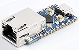
- 【RP2040-ETH Module】 Based On RP2040, Onboard Ethernet Port,Dual-core Arm Cortex M0+ processor, flexible clock running up to 133 MHz 264KB of SRAM, and 4MB of onboard Flash memory.
- Onboard CH9120 with integrated TCP/IP protocol stack. 14 × multi-function GPIO pins, compatible with some Pico HATs.
- Castellated module allows soldering direct to carrier boards. Drag-and-drop programming using mass storage over USB. 8 × Programmable I/O (PIO) state machines for custom peripheral support. Controllable via network.
- Support multiple communication modes: Supports TCP Server / TCP Client / UDP Server / UDP
- Support C/C++, MicroPython, Arduino: Comprehensive SDK, Dev Resources, Tutorials To Help You Easily Get Started
Security
Ethernet gives a system access to higher-layer security mechanisms; the 10BASE-T1S physical layer does not secure an endpoint by itself. Replacing a gateway can remove a protocol-conversion boundary while exposing more devices to a common Ethernet domain. Plan device identity and authentication, secure boot and signed firmware, segmentation and access control, secure diagnostics, update handling, monitoring and resilience to denial of service or a compromised node. Physical access to an exposed bus also belongs in the threat model.
TSN and time synchronization
Do not infer a complete Time-Sensitive Networking feature set from the label “10BASE-T1S.” The physical layer, PLCA access coordination, IEEE 802.1AS/gPTP time synchronization and other TSN functions may be implemented by different endpoint, MAC, switch or system components. Microchip’s product announcement describes TSN-related capabilities in its products; confirm the precise functions and system support required for a design.
Independent reader supportYour contribution helps us test, update, and keep practical guides available for everyone.Where the white paper’s idea may apply
Factory and process automation
Distributed I/O, sensors, actuators and process instruments are plausible edge uses when traffic is modest and the shared segment helps simplify wiring. The case is not that every factory link should move to a 10-Mbit/s bus; backbone and aggregation traffic still need suitable higher-capacity links.
Quick wins for a faster PC:
Scan for outdated or missing drivers - takes under a minuteDriver Scan →Repair Windows errors before they cause bigger problemsFix Now →Automotive zonal networks
Low-bandwidth body, comfort and other edge functions may fit a zonal architecture that brings processing together and reduces wiring. Microchip announced AEC-Q100 Grade 1-qualified LAN8670/1/2 devices and functional-safety-ready positioning for ISO 26262 applications in its automotive product announcement. These are claims about specific components, not certification of a complete vehicle network; the cable, connector, ECU, software, EMC, safety mechanisms and architecture remain system responsibilities.
Best Value

- There are several options for this item, this option comes with a OV2640 camera + PoE module. For more package content details, please check the image 2
- Adopts ESP32-S3R8 high-performance chip with Xtensa 32-bit LX7 dual-core processor, capable of running at 240 MHz. Integrated 512KB SRAM, 384KB ROM, 8MB PSRAM and 16MB Flash memory. Integrated 2.4GHz Wi-Fi and Bluetooth 5 (LE) wireless communication, with an onboard antenna. Supports switching to use external an-tenna
- Onboard W5500 Ethernet chip for extending 10/100Mbps network port through SPI interface. Optional for PoE module to realize Power over Ethernet function (IEEE 802.3af-compliant)
- Onboard camera interface, compatible with OV2640, OV5640 and other mainstream cameras for image and video capture. Onboard USB Type-C port for power supply, program downloading, and debugging, more convenient for development use
- Onboard TF card slot for external TF card storage of pictures or files. Compatible with Pico header, onboard multiple peripheral interfaces, offering strong compatibility and expandability
Smart buildings and HVAC
Room controllers, lighting and occupancy devices, HVAC sensors and actuators, and other building endpoints may benefit from fewer wiring runs or gateways. Existing conduit, power delivery, installation practice, environmental conditions and maintenance skills may matter more than the nominal bit rate.
When another option is better
- Choose faster switched Ethernet or a faster Single Pair Ethernet link when endpoints need sustained high bandwidth.
- Retain CAN, RS-485 or fieldbus when existing qualified equipment and tools are adequate and conversion costs outweigh the integration benefit.
- Use a hybrid design when some endpoints need a shared low-rate segment while others need higher throughput, stronger isolation or independent fault domains.
- Reconsider the bus when its length, topology or environmental conditions cannot be validated to the applicable channel requirements.
- Do not rely on PLCA alone where the required end-to-end timing guarantee exceeds what the configured network can demonstrate.
How to validate a design
VIAVI’s 10BASE-T1S technology overview and testing guidance frame this as a channel and protocol validation task, not just a routine cable check. Test the intended configuration before committing it to production:
- Establish physical link operation with the selected devices and host software.
- Test the longest intended cable, maximum node count and worst-case stub arrangement.
- Exercise maximum expected traffic and measure PLCA latency and jitter under load.
- Test coordinator restart or failure, node insertion and removal, and recovery behavior.
- Check interoperability across the chosen PHYs and relevant host drivers.
- Run ESD, EFT, surge and EMC tests appropriate to the application, and check operation across temperature and supply-voltage extremes.
- If PoDL is present, test voltage drop, startup, load transients, power noise and protection behavior.
- Verify firmware updates, fault isolation and diagnostic reporting under realistic bus load.
What the white paper establishes—and what it does not
The paper is a vendor-associated case for taking Ethernet toward edge devices through 10BASE-T1S. Its architectural promise—less cabling and fewer protocol islands in suitable designs—is credible as a design objective, but no topology removes the need for power engineering, channel validation, fault planning, security and lifecycle support. “All Ethernet” is not automatically a system-level win, and no PHY feature alone makes a complete network deterministic, secure or qualified.
Do these 3 things before closing this tab:
1Scan for outdated or missing drivers - takes under a minute2Repair Windows errors before they cause bigger problems3Fix the driver behind crashes, sound loss and screen glitchesFor implementation examples, Microchip provides product and evaluation information. The white paper is associated with onsemi, whose factory-network Ethernet controller design page is one of its product-design destinations. Product fit depends on host interface, operating range, qualification, software support and reference-design availability; the cited material does not establish current pricing or stock.
Quick Recap
Product prices and availability are accurate as of the date/time indicated and are subject to change. Any price and availability information displayed on Amazon at the time of purchase will apply.

