
The Tool Desk
Outbyte Driver Updater FREEScan for outdated or missing drivers - takes under a minuteDriver Scan →Outbyte PC Repair FREERepair Windows errors before they cause bigger problemsFix Now →iTechGuides is reader-supported. When you buy through links on our site, we may earn an affiliate commission. As an Amazon Associate I earn from qualifying purchases. Learn more
Use a boost LED driver when the LED string’s forward voltage is higher than the available DC supply. Use buck-boost when the supply can fall below or rise above the voltage the string needs. In either case, the driver must regulate LED current—not simply hold an output voltage—because LED forward voltage varies with current, temperature, and device variation.
Choose the topology by comparing supply voltage with LED-string voltage
Start by estimating the string’s total forward voltage across its operating conditions: LED current, temperature, and device variation. Then compare that range with the DC input range.
- Supply stays above the string voltage: a buck driver steps the voltage down.
- Supply stays below the string voltage: a boost driver steps it up.
- Supply range crosses the string voltage: a buck-boost topology or a two-stage design can accommodate both step-down and step-up operation.
A boost converter is a straightforward way to place more LEDs in series than the input voltage could otherwise support. A longer series string can simplify current matching among the LEDs, but it raises the required output voltage and does not remove the need to regulate current. A typical white InGaN LED may have a forward voltage from 3 to 4 V depending on process, drive current, and die temperature; designing around a single nominal voltage can therefore leave inadequate operating margin. Analog Devices’ LED-driver topology discussion describes the boost choice and its design considerations.
Quick wins for a faster PC:
Scan for outdated or missing drivers - takes under a minuteDriver Scan →Repair Windows errors before they cause bigger problemsFix Now →When a boost driver is the right choice
Choose boost when the maximum required LED-string voltage exceeds the available input voltage and the input does not need to be stepped down below the string voltage. For example, a lower-voltage DC source can drive a higher-voltage series LED string through a boost stage, subject to the driver’s output-voltage limit and current rating.
#1 Best Overall
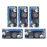
- 5pcs LM2596 Constant Current Led Driver DC-DC 3A Adjustable 7V-35V Step-down CC/CV Power Supply Module LM2596 Constant Current Voltage Regulator
- Input voltage: 7V-35V
- Output voltage: 1.25V-30V
- Output current: adjustable maximum 3A
- Conversion efficiency: 92% (the highest)
Account for rising inductor current
In continuous-conduction mode (CCM), the average boost-inductor current is approximately the LED load current divided by one minus the duty cycle: IL,avg = ILED / (1 − D). As duty cycle rises, average inductor current rises too. Check the inductor, switch, and current limit at the combination of minimum input voltage and maximum LED-string output voltage—not only at nominal supply conditions.
Plan for output ripple and control response
A boost converter’s output current is discontinuous, so an output capacitor is needed to keep LED current continuous between switching events. A smaller capacitor can improve transient response and dimming speed, but only if the resulting LED ripple current stays within the LEDs’ limits. The capacitor also has to tolerate the converter’s voltage and ripple-current conditions.
Rank #2

- 【Precision Voltage and Current Control】 Adjustable output voltage from 0.6V to 36V and current limit from 0A to 5A. Delivers precise CNC regulation with fast response, ensures accurate, stable, and consistent output for sensitive electronics.
- 【Smart Cooling System】 Features a high-efficiency heat sink and an intelligent temperature-controlled fan. The fan automatically activates when the module exceeds 50°C or when the current goes over 1A, providing efficient heat dissipation and extending product lifespan.
- 【Clear LCD Real-Time Monitoring】 Built-in LCD display shows input/output voltage, current, power, capacity, time, and temperature at a glance. Convenient for real-time monitoring and fine-tuning of your power settings.
- 【Comprehensive Protection for Safe Operation】 Equipped with multiple safety mechanisms including reverse connection, backflow prevention, undervoltage, overvoltage, overcurrent, overpower, overheating, timeout, and overcapacity protection. Ensures your electronic devices run reliably in a safe environment.
- 【High Efficiency and Wide Applications】 Delivers up to 80W with about 88% conversion efficiency, reducing energy loss and ensuring stable performance. Compact and lightweight design makes it perfect for DIY electronics, laboratory power supplies, and versatile voltage regulation needs.
When buck-boost is worth its added complexity
Choose buck-boost when the input range can be either lower or higher than the LED-string voltage. Automotive lighting is a representative case: the supply can move across the load voltage, so a converter may need to step up at one input condition and step down at another.
Outdated Drivers Are Slowing You Down
One free scan finds every outdated or missing driver and matches the right update for your exact hardware.Free scan · exact hardware matchWindows Errors? Fix Them Before They Spread
Repair common Windows errors and clear accumulated junk for a smoother, more stable PC - no reinstall needed.Free scan · no reinstallOne cited automotive example uses three 3-watt white LEDs at about 12 V and 1 A. Its normal vehicle-supply range is 9–16 V. The example also discusses an extended 6–42 V range in which performance is reduced but operation can continue without damage. Those figures describe that example, not a universal vehicle-supply specification or a guarantee for other drivers. The original Analog Devices article provides the context.
Rank #3

- Output Voltage: 0.5-30V; Output Current: It can Work Stably at 3A for a Long Time, and it can Reach 4A with Enhanced Heat Dissipation. Output Power: 35W ( Natural Heat Dissipation); 50W( Enhanced Heat Dissipation)
- Input Voltage: 5.5-30V (when the Input Voltage is 5V, it can also Realize Buck-Boost, but the Measurement of Voltage and Current is Not Accurate; when it is Lower than 4.7V, it will be Under-Voltage Protection)
- With LCD Display: The Voltage Regulator Module is Equipped with an LCD Display that Can Display Input and Output Voltage, Output Current and Output Power. Voltage Resolution is 0.01V, Current Resolution is 0.002A
- DC-DC Buck Boost Converter Module can be Boosted and Bucked, the Output voltage can be Adjusted Arbitrarily from 0.5-30V, and the Limit Current can be Adjusted Arbitrarily from 0-4A. The Button Controls the ON/OFF State of the Output Terminal, and can be set to be ON or OFF by Default after Power-On
- Applications: The Power Supply Can be Used for Power Supply, as a Voltage Limiter, as a Charger, as a High-Power LED Constant Current Driver Module or for Boosting and Reducing Voltage with Over-current Protection. It is not Necessary to Add an Anti-backflow Diode when Used as a Charger as the Output is Protected by the Diode
Buck-boost stages can have greater peak switch stress, more components, and lower efficiency than buck or boost alternatives. In common arrangements, energy is stored and transferred through magnetic or electric fields rather than being passed directly from input to output throughout the switching cycle; this tends to increase peak switch current or voltage. Check the actual topology and component ratings rather than assuming one stress pattern applies to every implementation.
Topology differences that affect the design
| Topology | Input and output behavior | Notable design consideration |
|---|---|---|
| Single-inductor buck-boost | Can step up or step down; some basic implementations invert output polarity. | Confirm polarity, peak switch stress, and the controller’s supported operating range. |
| SEPIC | Can step up or down with positive output polarity and continuous input current. | Account for its component count and the stresses of its energy-transfer components. |
| Ćuk | Can step up or down and offers continuous input and output currents, with inverted output polarity. | Polarity and implementation complexity may rule it out for a particular load. |
These are broad topology traits, not a substitute for a specific controller’s data sheet. A two-stage architecture can also separate the job of adapting the supply range from the job of regulating LED current, at the cost of another conversion stage.
Rank #4
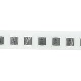
- High-Performance Power Inductor: designed with 47UH inductance and high current capacity, ideal for power supply circuits, DC-DC converters, LED drivers and automotive electronics, ensuring stable energy storage and noise suppression.
- Durable Molded Structure: a rugged molded resin construction that enhances mechanical stability, reduces core loss, and resists vibration, heat and humidity for long-term reliability in harsh environments.
- Compact SMD Design: surface-mount package with 0630 footprint (7 x 7 x 3 mm) for space-saving PCB layouts, compatible with automated assembly processes to improve production efficiency.
- Wide Application Compatibility: operates within a temperature range of -40 C to +125 C and supports high-frequency circuits, suitable for consumer electronics, industrial equipment, IoT devices and communication systems.
- Cost-Effective Bulk Pack: includes 30 pieces per pack, offering a budget-friendly solution for prototyping, repairs or mass production while maintaining consistent quality and performance.
Why boost and buck-boost can complicate fast PWM dimming
Do not assume that a boost or buck-boost driver can switch LED current off and on as quickly as a buck driver. In CCM, boost and buck-boost converters have a right-half-plane zero that limits practical control-loop bandwidth: increasing duty cycle does not produce the expected immediate increase in output response. That makes very fast PWM dimming more difficult to control.
When the LEDs turn off, energy already stored in the converter can also cause output-voltage excursions. The design needs suitable protection, a way to manage that stored energy, or a dedicated LED-driver IC designed for the dimming behavior. For demanding fast-PWM requirements, a buck second stage or a series switch that interrupts LED current can be more practical than relying on the boost or buck-boost control loop alone. Analog Devices’ switching LED-driver discussion covers the topology and control limitations.
Best Value

- 3Pcs Buck Boost Converter DC-DC Adjustable Step Up Down Converter XL6009 Power Supply Module 20W 5-32V to 1.2-35V
- Input Range:5V ~ 32V
- Output Range:1.25V ~ 35V
- Switching frequency:400KHz
Compare the trade-offs before selecting a driver
| Design factor | Boost | Buck-boost |
|---|---|---|
| Input range versus string voltage | Best when the string voltage is higher than the input. | Useful when the input range crosses the string voltage. |
| Efficiency and complexity | Often simpler than a buck-boost design, but efficiency depends on operating conditions and implementation. | Generally more complex and typically less efficient than buck or boost. |
| Current and voltage stress | Inductor average current rises with duty cycle; verify the low-input, high-output condition. | Peak switch stress can be higher; verify the selected topology’s worst-case ratings. |
| Output capacitor | Required to smooth discontinuous output current; size it against ripple and response needs. | Requirements depend on the exact topology and control arrangement; consult its design documentation. |
| Fast PWM dimming | CCM right-half-plane zero limits control bandwidth. | CCM right-half-plane zero also complicates high-bandwidth control. |
Boost and buck-boost designs are not automatically the preferred choice simply because they can raise voltage. A 2008 technical article notes their higher complexity and component count, lower efficiency—especially for buck-boost—and limited choice of control topologies compared with alternatives. That is a general trade-off, not a claim that every modern implementation performs alike; evaluate the specific controller and operating point. See the Analog Devices topology article.
Quick Recap
Selection checklist for a long LED string
- Establish the load range: determine the LED count and total forward-voltage range at the intended current and across minimum and maximum operating temperatures.
- Establish the input range: use the real minimum and maximum DC supply, including the conditions the system must survive or operate through.
- Match the topology: select buck if the supply remains above the string, boost if it remains below, and buck-boost or two-stage conversion if the ranges cross.
- Verify regulated current: confirm the driver regulates LED current over the complete input and load range, and that its output-voltage ceiling is sufficient.
- Check electrical and thermal limits: assess inductor and switch stress, current limits, component temperature, thermal rating, and protection behavior at worst-case conditions.
- Confirm dimming requirements: check the supported dimming interface and PWM frequency, and account for output excursions when LED current is switched off.
- Review implementation details: check switching frequency, output-capacitor requirements, polarity, component count, and the controller’s documented operating modes.
Product prices and availability are accurate as of the date/time indicated and are subject to change. Any price and availability information displayed on Amazon at the time of purchase will apply.

