
A practical rollover-stability development workflow combines a vehicle-specific nonlinear model, a Simulink controller, parameter optimization, and closed-loop verification in CarSim–Simulink cosimulation. A 2008 SAE paper by Vinod Cherian, Rohit Shenoy, Alec Stothert, Justin Shriver, Jason Ghidella, and Thomas D. Gillespie applies this approach to a midsize SUV and benchmarks its behavior with and without the optimized controller using the NHTSA fishhook maneuver. The work is a development methodology—not evidence that one controller or result applies to every vehicle.
What does a model-based rollover-control workflow involve?
Model-Based Design means developing and evaluating the control logic against models before committing to production software and vehicle testing. In the 2008 SAE workflow, CarSim supplies the nonlinear midsize-SUV vehicle model, Simulink hosts the stability controller, optimization is used to tune controller parameters, and CarSim–Simulink cosimulation tests the closed loop. MathWorks describes the work as a methodology to “develop and automatically optimize vehicle stability control systems.”

- Define the safety and control problem. Convert vehicle-level rollover concerns into explicit requirements, operating conditions, measurable stability objectives, and constraints on intervention. Identify hazards and assumptions before optimizing a controller.
- Build and validate the plant model. Represent the target vehicle’s relevant nonlinear behavior, including suspension, tires, load transfer, and actuator response to the extent needed for the design. Validate the model against available vehicle data and intended operating conditions; simulation results are only as credible as the model and its validation.
- Implement the control logic in Simulink. Organize the logic to estimate or use roll-related states, recognize when the vehicle approaches an unsafe region, and select interventions that address rollover risk without undermining yaw stability or controllability.
- Optimize parameters against defined objectives. Use a constrained objective that rewards stability while accounting for undesirable interventions and other vehicle-control requirements. Optimization can search parameter values; it cannot make an unsuitable model, objective, or safety requirement valid.
- Verify in closed-loop cosimulation. Connect Simulink and CarSim so the controller’s commands influence the simulated vehicle and the vehicle response feeds back to the controller. Test the target maneuver and a broader set of conditions, then compare baseline and controlled behavior using the same model and scenario.
- Build the evidence chain toward vehicle testing. Progress from model and controller checks to scenario-based closed-loop simulation, fault cases, and controlled proving-ground validation. Simulation supports development but does not by itself establish production-vehicle effectiveness.
The original paper is dated April 14, 2008. Its results concern its midsize-SUV model and must not be generalized to other SUVs, passenger cars, or vehicle platforms without vehicle-specific modeling and validation.
How should the controller be structured and tuned?
The controller should be designed around an explicit chain from sensing and state estimation to risk detection and actuator command. Exact thresholds, state definitions, sampling rates, and parameter values are vehicle- and implementation-specific; the cited SAE summary does not establish universal values.
Recommended Free Tools
#1 Best Overall

- Controls 2 Windows
- Windows up & down with learn function
- Power-window automation system
Estimate roll-related behavior
Determine which measured signals and estimated states are available and sufficiently reliable for the target vehicle. Candidate indicators include roll angle, load-transfer measures, wheel-lift indications, or a model-predicted stability boundary. These are design alternatives, not interchangeable measurements: each has different sensing, estimation, and validation needs.
Define the intervention region and objectives
Specify what constitutes an approach to an unsafe operating region and how early intervention should begin. Balance rollover mitigation against yaw stability, driver control, and smoothness. Test both the trigger boundary and transitions into and out of intervention so that abrupt or unnecessary commands are not hidden by a favorable peak-stability metric.
Rank #2
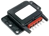
- Professional, premium aftermarket replacement
- Provides the performance and dependability you expect from ACDelco
- Manufactured to meet expectations for fit, form, and function
- International products have separate terms, are sold from abroad and may differ from local products, including fit, age ratings, and language of product, labeling or instructions
Choose actuators available on the vehicle
Differential braking is one possible means of generating corrective vehicle forces; torque intervention, steering, active suspension, or coordinated actuation may also be considered when supported by the vehicle architecture. Include actuator authority, delay, limits, and failure behavior in the model. Do not assume that an actuator available in one platform is available or appropriate in another.
Optimize for more than one successful maneuver
Set the optimization objective and constraints before parameter search. Assess stability indicators alongside yaw response, command activity, actuator saturation, and sensitivity to uncertainty. Retain scenarios not used for tuning as independent checks; otherwise, parameter optimization can overfit the selected maneuver or nominal model.
Windows Errors? Fix Them Before They Spread
Repair common Windows errors and clear accumulated junk for a smoother, more stable PC - no reinstall needed.Free scan · no reinstallOutdated Drivers Are Slowing You Down
One free scan finds every outdated or missing driver and matches the right update for your exact hardware.Free scan · exact hardware matchRank #3

- 【Real-time wheel speed monitoring for emergency braking】 This ABS anti-lock braking control unit collects signals from all four wheel speed sensors in real time and independently adjusts braking oil pressure during emergency stops. The system prevents wheels from locking, retains steering control, and helps avoid skidding or loss of control on wet or slippery surfaces – giving you confident stopping power when you need it most
- 【Integrated traction and stability control for all-weather safety】 Built-in Traction Control System (TCS) and Electronic Stability Control (ESC) logic work together to inhibit drive wheel slip on wet roads and correct vehicle body posture during sudden maneuvers. Whether you're navigating rain-soaked highways or uneven off-road terrain, this module helps keep your Wrangler planted and under control
- 【Direct replacement for failed or faulty ABS modules】 This integrated assembly includes the hydraulic valve body, solenoid valves, and drive chip – all in one unit for straightforward replacement. When your original module fails, the instrument ABS warning light illuminates, and both ABS and anti-skid stability systems become inoperative. This direct-fit replacement restores full braking functionality without complex modifications
- 【Restores braking performance and clears common fault codes】 Effectively resolves typical issues including: ABS warning light staying on, abnormal pump operation, internal module failure (C2200), and brake system communication failure. The module communicates with the engine control unit and stores ABS fault codes, making it easier to diagnose and clear issues during servicing
- 【Durable ABS and metal construction for long-term reliability】 Built from high-strength ABS and premium metal materials to withstand harsh driving conditions. The durable construction ensures consistent performance and long service life, meeting strict manufacturing standards for reliability in off-road and demanding driving environments. Note: After replacement, the module requires professional programming and matching using specialized equipment
Related IEEE work describes a three-dimensional dynamic stability controller coordinating yaw stability, yaw–roll stability, and rollover prevention with active braking and model-predictive prediction. That is a separate research approach; the 2008 SAE workflow should not be described as using model-predictive control.
How do CarSim and Simulink work together?
CarSim represents vehicle dynamics, while Simulink represents the control logic in this workflow. Cosimulation exchanges vehicle states and controller commands so the controller can be evaluated against the modeled response. This is useful because the vehicle’s nonlinear response and the controller’s interventions interact; evaluating control logic in isolation would not show that closed-loop behavior.
Rank #4

- Product Type:Auto Part
- Item Package Dimensions:6.5 " L X 6.3 " W X 2.3 " H
- Item Package Weight:1.05 lbs
- Country Of Origin: United States
The MATLAB Central example associated with the work lists Simulink, Optimization Toolbox, Simulink Design Optimization, and CarSim 7.0 or higher as requirements. Its package version is 1.3.0.2, updated August 6, 2020. These are the example’s listed requirements, not confirmation of present-day compatibility. Check current product and example compatibility before attempting reuse.
What is the NHTSA fishhook maneuver used for?
The fishhook is a dynamic maneuver used in the SAE work to estimate rollover stability and benchmark the SUV with and without the optimized controller. The meaningful comparison is between baseline and controlled runs under the same vehicle model and maneuver, using defined rollover and vehicle-response measures.
The Tool Desk
Outbyte PC Repair FREEClear out junk files and repair common Windows errorsFree Scan →Outbyte Driver Updater FREEScan for outdated or missing drivers - takes under a minuteDriver Scan →A successful result in this maneuver is evidence about that modeled scenario, not a general rollover-risk reduction percentage. No independently generalizable current production-vehicle effectiveness figure is established by the cited sources. A development program should add scenarios that cover its requirements and operating envelope rather than treating one benchmark maneuver as complete validation.
Independent reader supportYour contribution helps us test, update, and keep practical guides available for everyone.Which modeling and control choices should be compared?
Model fidelity, risk indicators, actuation, computation, robustness, and safety evidence should be considered together. A more complex controller is not automatically safer if it depends on unavailable signals, exceeds computation limits, or is fragile to model mismatch.
| Design axis | Options to assess | Key question |
|---|---|---|
| Vehicle model | Linear or nonlinear representation; fidelity in suspension, tires, load transfer, and actuators | Does the model capture the behaviors that govern the safety objective in the relevant conditions? |
| Rollover indicator | Roll angle, load-transfer metric, wheel-lift indication, or predicted stability boundary | Can the indicator be measured or estimated reliably and early enough for intervention? |
| Actuation | Differential braking, torque or steering intervention, active suspension, or coordinated combinations | What authority, delay, limits, and failure modes apply on this vehicle? |
| Computation and robustness | Sampling time, actuator delay, uncertainty, sensor noise, and off-nominal behavior | Does the controller remain stable and within execution limits when assumptions vary? |
| Safety evidence | Requirements traceability, verification scenarios, fault handling, and safety work products | Can each safety requirement be linked to implementation and verification evidence? |
How does ISO 26262 apply?
ISO 26262 concerns functional safety for safety-related electrical and electronic systems in series-production road vehicles. ISO 26262-10:2018, dated December 2018, provides guidance for understanding the ISO 26262 series. It is guidance within the standard series, not a substitute for applying the relevant lifecycle requirements to a particular system and vehicle program.
For model-based control development, safety considerations should shape the models and evidence from the outset. SAE research on model architectures discusses applying ISO 26262 architectural principles to Simulink models, including metrics and methods intended to reduce model complexity. The practical objective is not simply a cleaner model: it is a model and development process that support review, traceability, verification, and safety analysis.
Use a staged evidence chain
- Requirements and hazard analysis: define safety goals, operating assumptions, interfaces, and required behavior under normal and degraded conditions.
- Plant-model validation: document the model’s basis, validated conditions, and known limitations.
- Controller verification: test units and the integrated model-in-the-loop behavior against requirements, boundary conditions, and expected failure responses.
- Implementation checks: use software-in-the-loop and processor-in-the-loop tests where applicable to check implementation behavior and execution constraints.
- Scenario and fault testing: exercise closed-loop scenarios, sensor faults or degradation, actuator limitations, and uncertainty cases.
- Vehicle validation: confirm behavior through controlled proving-ground testing before making claims about vehicle-level effectiveness.
This sequence is a development recommendation. The cited papers support the model-based and safety-architecture rationale, but do not specify a complete compliance plan for every program.
Quick Recap
Product prices and availability are accurate as of the date/time indicated and are subject to change. Any price and availability information displayed on Amazon at the time of purchase will apply.

