
Do these 3 things before closing this tab:
1Fix the driver behind crashes, sound loss and screen glitches2Clear out junk files and repair common Windows errors3Scan for outdated or missing drivers - takes under a minuteYes—a microcontroller can drive a WS2811 from SPI through a one-transistor conditioning stage, but the circuit is not automatically reliable just because the parts are simple. The first pixel is the weak link: its input needs correctly timed pulses with sufficient voltage margin and clean edges. Keep that connection short, account for any inversion in the SPI data, and verify the waveform at the WS2811 DIN pin.
How the one-transistor driver works
The minimal approach reported by Mike Szczys at Hackaday in 2014 uses one transistor, three resistors and a capacitor. It puts a transistor stage between the microcontroller’s SPI MOSI output and the first WS2811 DIN input. The transistor can condition and level-shift the signal, while the resistors set input and output behavior and the capacitor bypasses the LED driver’s supply.
A common implementation uses an NPN transistor in a common-emitter arrangement: MOSI drives the base through an input resistor; the collector is pulled up to the WS2811 logic supply; and the collector drives DIN through a series resistor. That arrangement inverts the data: MOSI low produces a high at the collector, and MOSI high pulls the collector low. Firmware encoding must compensate for that inversion. Confirm the selected transistor’s pinout and ratings rather than assuming every small-signal NPN has the same lead arrangement.
The three-resistor count describes a compact reported approach, not a universal schematic or a guaranteed set of values. The Hackaday account does not establish a resistor-value set suitable for every transistor, supply, cable or LED assembly. Treat the base resistor, collector pull-up and data-series resistor as design choices to validate with the actual circuit. World-Semi’s WS2811 V1.4 datasheet recommends a 33 Ω resistor on the data input or output for impedance; it is a useful starting point for the data-series position, not a substitute for checking the waveform.
#1 Best Overall

- Support PWM LED Strip. PWM LED strip which has no IC chip,fox example FCOB 5630 5730 5050 2835 3528 2pin(V+ V-) 3pin CCT(V+ CW WW) 4pin RGB(V+ R G B) 5pin RGBW(V+ R G B W) 6pin RGBCCT(V+ R G B CW WW) .Monochrome Light and CCT light have no function of DIY light effect.
- Support Addressable IC Chip LED Strip. SPI TTL IC Chip LED strip. 3pin(V+ Data GND) or 4pin(V+ Data Backup GND). For example WS2811 WS2812B WS2813 WS2814 WS2815 SK6812 LB1934 IC chip etc single color, CCT, RGB, RGBW, RGBCCT addressable LED strip. Can not support SK9822 WS2801 etc Data+Clock LED strip. Monochrome Light and CCT light have no function of DIY light effect.
- The SP630E controller's SPI interface supports a maximum of 600 ICs for single-color LED strips, 600 ICs for CCT (dual-color-temperature) LED strips, 600 ICs for RGB LED strips, 450 ICs for RGBW LED strips, and 300 ICs for RGBCCT LED strips, with all values representing the upper control limits under optimal operating conditions.
- Support SPI+PWM LED Strip at the same time.For example you can controller WS2812B IC RGB LED strip + FCOB 3000K single color no IC strip or WS2812B IC RGB LED strip + FCOB CCT no IC strip.
- DIY .You can make your own lighting effect for the LED strip.Banlan X APP bluetooth control .Three APP operating interfaces: static effect, dynamic effect and music effect.Great for DIYers, renovators, pros, and beginners for cabinets, shelves, TV backs, offices, RVs, or PCs. (Note:Only when the parameter settings of all SP630E are consistent can the APP grouping function be used.)
Place a bypass capacitor directly across the WS2811 supply pins. A 100 nF capacitor is a practical starting component for local high-frequency bypassing, but it does not fix a poorly timed or noisy data signal. Keep LED power wiring and ground connections sound, and connect the microcontroller ground to the LED-driver ground so the signal has a shared reference.
Meet the WS2811 signal requirements
The WS2811 is a single-wire, pulse-width-coded device. Its V1.4 datasheet specifies a 3.5–5.5 V supply and an 800 kHz oscillator frequency. That oscillator figure is not the SPI clock to select: the data input distinguishes zero and one by pulse widths.
Rank #2

- Music Rhythm Synchronization:3 types of capture, phone microphone, player streaming, built-in microphone. Built-in high-sensitivity microphone that automatically adjusts the light and spectrum according to the ambient sound. There are 18 kinds of music effects for you to choose. Connect with smartphone app via Bluetooth(Please browse picture 2 or read the connection in the manual carefully)NOTE:Not suitable for RGB LED strip lights without smart IC
- Support Driver IC Models:Work with PAUTIX RGB Smart IC COB LED strip light(ASIN:B0BN5N3R82). Support almost all LED driver chips in the market, such as WS2811, WS2812B, US1903, WS2801, etc. Control up to 600 pixels. the output voltage of LED strip and power supply must be the same. If you use 24V LED strip, you must use DC24V power supply, not 12V (LED strip and power supply are not included).
- Rich Color Effects:142 built-in dynamic effects and many static color effects. There are 142 kinds of dynamic effects, such as rainbow, twinkling stars, waves. You can set the speed, effect length and brightness as needed. Also, you can choose 9 effects to collect for next time. You can directly slide the RGB values of colors in static effects.
- Timer function:Up to 5 timers can be set. Timer function you can set the same time every day to light up the ribbon and you can choose the light effect to be lit up. The controller can not cut off the power, otherwise it will clear the alarm record. Up to 5 timers can be set. With memory function in case of power failure.
- 3 Ways to Control:App, IR remote control and box button. Use Android 4.4/IOS 1.0 or higher smartphone, search for "SceneX” in App Store or Google Play. use the remote control to make it work without the app. The app can adjust the speed, brightness. 5.5mmx2.1mm DC power socket. If the effect is stuck or the end of the LED strip is getting dim, please add voltage to the LED strip in time. This is a normal physical phenomenon and all LED strips are not immune to this problem.
| Signal parameter | WS2811 V1.4 specification |
|---|---|
| T0H, high time for a zero | 220–380 ns |
| T1H, high time for a one | 580 ns–1 µs |
| T0L, low time for a zero | 580 ns–1 µs |
| T1L, low time for a one | 580 ns–1 µs |
| Reset | Low for more than 280 µs |
SPI acts as a timing source by representing each LED bit with several SPI bits. The ws2811-spi documentation gives 1.6–3.2 MHz as the supported peripheral-clock range for its normal variant; it also offers a prerendered variant for systems that cannot continuously generate the data. Those figures apply to that software’s documented variants, not to every SPI implementation or every encoding.
Choose an encoding that produces WS2811-compliant high and low intervals after the transistor stage, including its inversion. Do not assume a generic WS28xx bit pattern will work unchanged. The WS2811 datasheet specifies 24 bits per device in RGB order, most-significant bit first: R7 through R0, then G7 through G0, then B7 through B0. The chip reshapes the signal for the next device in the chain.
What’s actually slowing this PC down?
Pick the symptom - the matching free tool is one click away.
Rank #3
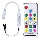
- Input voltage:DC5V/DC12V/DC24V; Input current:5A max, please don't use for project that draws more than 5A current.
- SP103E controller supports 5V WS2812B and 12V/24V WS2811LED lights.It can’t control SK6812 RGBW LED lights and regular RGB LED without driver IC.
- Contain 200 kinds of color modes, such as rainbow, wave, breathing, strobing, gradual change, color cycle, comet, static, fading, chasing, which are vivid and beautiful. Color changing speed and brightness are adjustable.
- 15m long distance wireless RF remote control; mini size; convenient to use. DC 5V~24V input; But it can’t regulate the output voltage.Please choose power supply according to your led lights, not the controller.
- Support setting controlled pixels number. Control up to 2048 pixels at most. R/G/B keys can be reordered to match with your LED light if needed.
Check voltage levels and signal margins
For the WS2811, the guaranteed input-high threshold is 0.7 × VDD and the input-low threshold is 0.3 × VDD. At a 5 V supply, that means a high must reach at least 3.5 V and a low must be no more than 1.5 V. A 3.3 V microcontroller output may work with short, clean wiring, but it does not meet the datasheet’s guaranteed high threshold when the WS2811 is powered at 5 V.
The transistor stage can provide a signal referenced to the LED supply, improving high-level margin, but its output must still satisfy the timing limits. The datasheet’s absolute-maximum table gives the logic-input range as VDD−0.7 V to VDD+0.7 V. Keep the grounds common, and do not let the LED supply reach an MCU pin beyond that pin’s rating. A transistor’s presence does not make every wiring fault safe.
Rank #4

- Input voltage: DC5V/DC12V/DC24V; Input current: 4A max, please don't use for project that draws more than 4A current.
- 【Bluetooth Remote Control.】IOS and Android App remote control via Bluetooth ; IOS 10.0 or Android 4.4 or later edition required. 20m Long distance remote control; convenient to use. Your smart Phone should support Bluetooth 4.0 or later version.
- 【Wide Compatibility】 Support almost all the LED driver ICs, such as WS2811,WS2812B, SK6812, SK6812-RGBW. But there is no WS2812B option on the setting page, please choose WS2811 when connect it to WS2812B LEDs.
- 【Rich color modes】Come with 120 kinds of dynamaic color change modes, tons of static color, which are vivid and beautiful. Color hue, brightness and speed are adjustable. When you connect SK6812-RGBW LED Strip, the white channel can be adjusted individually.
- 【User-friendly design】Support setting IC types, R/G/B sequence and pixels number, control up to 1024 pixels in total. Save user setting when power off. DC 5V~24V wide working voltage; reverse connection protection; hot swap protection.
Choose between direct drive, a transistor and a translator
| Approach | High-level margin | Inversion and firmware | Edge behavior and wiring | Trade-off |
|---|---|---|---|---|
| Direct 3.3 V drive into a 5 V WS2811 | Not guaranteed by the 0.7 × VDD input-high threshold | No added transistor inversion | Depends on output drive, wiring and input capacitance | Fewest components, but limited guaranteed-high margin |
| One-transistor stage | Can reference the collector pull-up to the LED logic supply | A common-emitter NPN stage inverts; firmware must account for it | Must be validated under the actual cable and input load; the first link is particularly sensitive | Small bill of materials, with more analog behavior to check |
| Dedicated logic-level translator | Depends on the chosen device and its supply arrangement | Depends on translator type | Check the translator’s speed, loading and wiring limits | More components than the minimal stage; choose from the device’s own specifications |
Direct drive can be a reasonable experiment on a short connection when it works, but it is not a guaranteed 5 V logic-high. A one-transistor stage keeps the component count low while making transistor choice, pull-up behavior, inversion and edge shape part of the design. A dedicated translator is another option; its suitability depends on its own data sheet and the signal conditions. None of these options removes the need to check the signal at the first pixel.
Keep the first-pixel connection short
Hackaday’s report describes the measured edges as insufficiently clean for a long connection before the first pixel. The practical implication is to put the first WS2811 close to the driver and avoid adding cable, connectors or abrupt wiring changes before DIN unless measurements show adequate margin. Cable capacitance and connector transitions affect edge shape and therefore belong in the timing budget.
The WS2811 has a built-in signal reshaper: after receiving its own data, it retransmits a reshaped signal to the next device. That can help downstream pixels, but it does not repair the link from the MCU or transistor to the first pixel. Put the bypass capacitor at the WS2811 supply pins, and use the recommended 33 Ω data resistor as a starting point with placement appropriate to the driver and layout.
Quick Recap
Bring up the SPI waveform before extending the strip
- Wire one pixel first. Connect MCU ground and LED ground together, keep the driver-to-DIN path short, and power the WS2811 within its 3.5–5.5 V supply range.
- Probe both sides of the transistor. Use a logic analyzer or oscilloscope to inspect MOSI and the signal at WS2811 DIN. A software setting or nominal SPI rate cannot reveal the actual edge shape, byte gaps or idle level at the pixel.
- Check clock and byte continuity. Confirm the actual SPI clock matches the chosen encoding and that there are no unintended gaps between bytes. The ws2811-spi documentation specifically warns that byte gaps, MOSI idle state and compiler optimization can alter the waveform.
- Verify polarity and idle state. Confirm whether the transistor inverts the signal, and check that DIN is low during the reset interval. The software documentation describes an idle-high option for cases where the hardware requires it; do not enable it without checking the resulting DIN waveform.
- Measure pulse widths and reset. At DIN, verify zero and one high/low times against the WS2811 limits and confirm a low interval longer than 280 µs between frames.
- Test the first pixel alone. Confirm its color and response before adding more pixels or lengthening the connection. Extend the cable or cascade only after the first link is stable.
Troubleshoot flicker, wrong colors or full-brightness output
- Wrong color order or channel values: Check the WS2811’s RGB, most-significant-bit-first sequence and the byte order emitted by your software. Do not assume another WS28xx device’s ordering applies.
- First pixel flickers or misreads data: Inspect DIN rather than relying on the MOSI clock setting. Look for marginal high voltage, rounded or noisy edges, pulse widths outside the specified ranges, or a long first connection.
- Full-brightness output or broad timing failures: Check the DIN idle level, the inversion introduced by the transistor, unintended gaps between SPI bytes and the actual pulse widths. The SPI documentation identifies voltage, idle-level and inter-byte timing problems as possible causes.
- Only later pixels behave differently: Test the first pixel and its supply and ground separately. Signal reshaping helps the link from one WS2811 to the next, but cannot correct a bad first link or inadequate power wiring.
- The circuit works only with one build or optimization setting: Measure the emitted waveform again. Compiler optimization and software data generation can affect timing; use the documented prerendered variant if continuous generation is not reliable, then validate its output on the hardware.
Product prices and availability are accurate as of the date/time indicated and are subject to change. Any price and availability information displayed on Amazon at the time of purchase will apply.

