
Quick wins for a faster PC:
Repair Windows errors before they cause bigger problemsFix Now →Fix the driver behind crashes, sound loss and screen glitchesFind Drivers →iTechGuides is reader-supported. When you buy through links on our site, we may earn an affiliate commission. As an Amazon Associate I earn from qualifying purchases. Learn more
There is no single relay for every 230 V AC load. Choose the device for the load’s type, running current, inrush current and switching frequency—not just its voltage. A correctly rated electromechanical relay is often a practical choice for a modest resistive load; use a motor-rated relay or contactor for motors, and consider an AC solid-state relay (SSR) for frequent, silent switching when its heat and leakage are acceptable. The coil or control-input voltage is a separate choice from the voltage switched by the contacts.
Safety: 230 V AC is hazardous mains voltage. Use appropriately rated, enclosed components and overcurrent protection. Have fixed wiring, high-power loads and motor installations designed or checked by a qualified electrician.

Choose by load, not by the 230 V supply
Start with the equipment being switched. A heater, LED driver, pump and safety interlock may all use 230 V AC but place very different demands on contacts. Use the load’s nameplate current and manufacturer documentation where possible; for motors, lamps, transformers and electronic power supplies, account for startup or inrush current as well as running current.
The Tool Desk
Outbyte Driver Updater FREEFix the driver behind crashes, sound loss and screen glitchesFind Drivers →Outbyte PC Repair FREEClear out junk files and repair common Windows errorsFree Scan →| Load or use | Likely device | What to check |
|---|---|---|
| Small resistive heater | Rated electromechanical relay or AC SSR | Continuous current, load category, duty and temperature derating |
| LED lighting or electronic driver | Inrush-rated relay, contactor or suitably specified SSR | LED/lamp or capacitive inrush rating; running watts alone can mislead |
| Fan, pump, compressor or other motor | Motor-rated relay or, commonly as power and duty increase, a contactor | Motor current, starting current, AC-3 or equivalent rating, starts per hour and overload protection |
| Solenoid, transformer or other inductive load | Device rated for that inductive or transformer load | Pickup/inrush current, suppression and switching frequency |
| Frequent, silent switching of a suitable AC load | AC SSR | Heatsinking, leakage, inrush, fuse and failure consequences |
| Emergency stop or guard interlock | Designed safety relay/system | Required safety architecture and application standards; an ordinary relay is not a substitute |
Separate the coil voltage from the contact voltage
A relay’s coil (or an SSR’s input) operates the switch; its contacts switch the load. Those sides have separate ratings. A relay can, for example, have a 24 V DC coil and contacts rated to switch a 230 V AC load. A 230 V load does not require a 230 V coil. For microcontrollers or other low-voltage controls, use a suitable isolated interface or relay module, and verify input voltage, input current and logic compatibility. A 230 V AC coil is appropriate only when the control supply and relay specification call for it. Manufacturer catalogs list coil and contact specifications separately; see TE Connectivity’s relay-selection overview and this Phoenix Contact relay example with a 230 V AC coil.
#1 Best Overall

- Input control signal: Voltage AC 174~286V, Current 3mA.
- Output switch DPST 1NO 1NC(Double Pole Single Throw, 1x Normally Open and 1x Normally Close ), rated current 8A/250VAC or 8A/30VDC (one switch).
- Compact plastic case and wires connects for easy mount. LED indication for relay action.
- This is a simple and practical passive relay module, which is very convenient to use. It can support both Normally Open and Normally Close. Two screw mounting holes are convenient for you to fix it on the wall or wooden board. Of course, you can also choose not to lock the screw.
Do not assume an optocoupler or a relay module makes an entire assembly safe for mains. Board layout, insulation spacing, terminals, enclosure and wiring must preserve the required separation.
Identify the load and estimate its current
Resistive loads
For a substantially resistive load, estimate running current with I = P ÷ V. At 230 V, 1,000 W is about 4.35 A and 2,000 W is about 8.70 A. These are approximate steady-state values, not a relay recommendation: check the device’s rating for the actual load category, switching duty, contact configuration and operating temperature.
| Load power | Approximate current at 230 V |
|---|---|
| 100 W | 0.43 A |
| 500 W | 2.17 A |
| 1,000 W | 4.35 A |
| 1,500 W | 6.52 A |
| 2,000 W | 8.70 A |
| 3,000 W | 13.04 A |
Motors and inductive loads
Motors, pumps, fans, compressors, solenoids and transformers can draw much more current at startup than while running. Inductive loads also create switching transients. Use the nameplate current, starting or locked-rotor current and the load’s documentation; choose a relay with an explicit motor or inductive rating. For motor switching, AC-3 is commonly associated with starting and stopping a motor; AC-4 covers more demanding inching, plugging and reversing duties. The applicable category and rating must match the actual use. See Omron’s AC-1 and AC-3 explanation and Schneider Electric’s utilization-category information.
Lamps and electronic loads
LED drivers, switching power supplies and some transformers can have brief, high inrush even when their steady-state wattage is low. Incandescent lamps can also draw substantial startup current. Check an explicit lamp, LED, capacitive or transformer rating rather than choosing from running current alone.
Rank #2
- Input control signal: Voltage AC 87~143V, Current 6mA.
- Output switch DPST 1NO 1NC(Double Pole Single Throw, 1x Normally Open and 1x Normally Close ), rated current 8A/250VAC or 8A/30VDC (one switch).
- Compact plastic case and wires connects for easy mount. LED indication for relay action.
- This is a simple and practical passive relay module, which is very convenient to use. It can support both Normally Open and Normally Close. Two screw mounting holes are convenient for you to fix it on the wall or wooden board. Of course, you can also choose not to lock the screw.
Choose an electromechanical relay, SSR or contactor
Electromechanical relay
An electromechanical relay (EMR) switches using physical contacts. It is often a good choice for occasional switching of a modest load when the contacts have the correct rating. It usually has low off-state leakage and does not need an SSR-style heatsink at modest current. Trade-offs include clicking, contact bounce, arcing and wear; electrical life depends heavily on load and switching conditions. A physical contact is not automatically an approved isolation device: confirm the relay’s insulation ratings and the properties of the complete assembly.
Solid-state relay
An AC SSR uses semiconductor switching, commonly a triac or thyristor output. It can switch silently and frequently, making it useful for suitable repetitive loads such as heating control. A zero-cross SSR turns on near the AC waveform’s zero crossing and is often suitable for resistive heating. A random-fire (instantaneous) type may be needed for phase-angle control or other applications. Neither type is suitable for every load; verify the manufacturer’s guidance for the load and switching method.
SSRs have important limitations: they leak a small current when off, create heat while conducting and may fail shorted, leaving the load energized. A small lamp or solenoid may glow, buzz or remain partly energized. At higher currents, thermal design and often a heatsink are essential; a headline current rating does not establish usable continuous current in a particular installation. Check Schneider Electric’s SSR catalog, its load and inrush cautions, and Panasonic’s SSR cautions.
Contactor
A contactor is generally the more suitable power-switching device as motor size, inrush or switching duty increases. Select it using the motor’s voltage and current, utilization category and operating duty; provide the required overload protection. A contactor is not automatically safer than a relay and still needs appropriate protection, wiring and enclosure.
Rank #3
Safety relay
For an emergency stop, safety door or guard-monitoring function, use a safety system designed for that function. Safety relays may use force-guided contacts and safety-specific circuitry, but are not interchangeable with ordinary control relays or a shortcut to making the surrounding system compliant. See Phoenix Contact’s PSR safety relay information.
Read the complete rating, not just “10 A”
A marking such as “10 A, 250 VAC” does not mean that the relay can switch every 10 A load at 230 V. Check the datasheet for the specific contact, voltage and load conditions. Manufacturers may give different values for resistive, inductive, motor, lamp or capacitive loads, as well as separate utilization categories and limits for different contact arrangements. One Schneider relay catalog, for example, lists different resistive, inductive and motor-load values rather than one universal current rating: Schneider relay ratings.
- Confirm the rated contact voltage and current at the relevant load category and local frequency, commonly 50 or 60 Hz.
- Check startup, locked-rotor or inrush ratings, switching frequency, ambient-temperature derating and the intended service life.
- Distinguish mechanical life from electrical life; the latter varies with the load being switched.
- Check whether the rating applies to normally open or normally closed contacts and to the chosen pole arrangement.
- For an SSR, check required heatsinking, mounting conditions, fuse recommendations and off-state leakage.
- Confirm insulation, dielectric withstand, creepage and clearance, applicable approvals, and the ratings of sockets, terminals and the assembled product.
For perspective, manufacturer product data is specific: these Phoenix Contact relay specifications include a 2 kV AC winding-to-contact test value, while a different Phoenix Contact relay lists overvoltage category III and a 2.5 kV RMS winding-to-contact test value. Those figures describe those products, not universal requirements for every relay or installation.
Outdated Drivers Are Slowing You Down
One free scan finds every outdated or missing driver and matches the right update for your exact hardware.Free scan · exact hardware matchWindows Errors? Fix Them Before They Spread
Repair common Windows errors and clear accumulated junk for a smoother, more stable PC - no reinstall needed.Free scan · no reinstallWorked selection examples
1,000 W heater
At 230 V, a 1,000 W resistive heater draws approximately 4.35 A in steady operation. A correctly rated EMR may suit occasional switching; an appropriately specified, heat-sunk AC SSR may suit frequent silent control. Confirm the actual load category, ambient-temperature derating, service life and protection rather than selecting a device solely because its label exceeds 4.35 A.
Rank #4
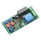
- With the start / stop function, after the start of the module into the infinite loop mode, the relay work in accordance with the set time.
- It is a timer relay module with high precision, stable and reliable performance.
- There is a wide time range that you can set, both "RUN" time and "STOP" time are adjustable.
- Support start/stop function, module enter an infinite cycle mode after power on, relay works according to the setting run and stop time.
- It is great to control the reciprocating stroke, or repetitive power on and off for equipment and products burn-in test.
100 W LED lighting circuit
The approximate running current is only 0.43 A, but LED drivers can have high inrush. Choose by the manufacturer’s LED or lamp-load rating for the number and type of drivers. An SSR also introduces off-state leakage, which may cause some lamps to glow or flicker.
0.25 kW fan motor
Do not select from the 250 W figure alone. Obtain the motor’s rated current and starting current, then use a motor-rated relay or contactor with an appropriate AC-3 or equivalent rating. Include overload protection as required by the motor and installation.
230 V solenoid
Check pickup and holding characteristics and the specified inductive-load rating. A suitable suppressor can reduce transients and contact stress, but must be rated for the AC circuit and installed as its manufacturer directs.
What’s actually slowing this PC down?
Pick the symptom - the matching free tool is one click away.
Microcontroller controlling a mains appliance
Use a properly designed, enclosed interface with a compatible low-voltage input and mains-rated contacts. Verify isolation and board spacing, terminal and enclosure ratings, fusing and the appliance’s inrush. Never connect a GPIO directly to 230 V or rely on an exposed hobby board as a mains-safe assembly.
Best Value
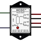
- This is a simple and practical passive relay module, which is very convenient to use. It can support both Normally Open and Normally Close.
- Input control signal: AC/DC 5V, AC/DC 12V, AC/DC24V, AC/DC48V, AC 115V, AC 230V Selectable.
- Output switch DPST 1NO 1NC(Double Pole Single Throw, 1x Normally Open and 1x Normally Close ), rated current 8A/250VAC or 8A/30VDC (one switch).
- LED indication for relay action.
- Compact ABS plastic case and wires connect for easy mount. Two screw mounting holes are convenient for you to fix it on the wall or wooden board. Of course, you can also choose not to lock the screw.
Contact poles, suppression and circuit protection
Choose contacts for the circuit
SPST-NO provides one normally open switched circuit; SPDT changes a common contact between normally open and normally closed; DPST or DPDT provides two poles. In mains wiring, the line/live conductor is the critical conductor to interrupt, and protective earth must never be switched by an ordinary control relay. Whether to switch neutral as well depends on the equipment, isolation needs and local wiring rules. Pole count alone does not make a relay an approved isolator.
Suppress inductive transients appropriately
An AC inductive load or coil may need an appropriately rated RC snubber, MOV or manufacturer-approved suppressor. A DC relay coil commonly uses a flyback diode with the correct polarity; that is not a general solution for an AC coil. Suppression can affect release time, so follow the relay and load manufacturers’ instructions. See TE Connectivity’s relay application notes and Omron’s contact-protection guidance.
Protect and enclose the installation
A relay’s contact rating does not replace branch-circuit overcurrent protection. A mains assembly also needs protection and construction appropriate to the circuit and local rules, including suitable fuse or circuit-breaker coordination, enclosure, strain relief, terminals, wire insulation, protective-earth continuity where applicable, and adequate insulation spacing. SSRs require thermal design and consideration of their shorted failure mode; where unintended continued energization would be hazardous, provide a separate means of isolation appropriate to the system. Fixed wiring, high-power heaters and motor installations should be designed or checked by a qualified electrician.
Common failure modes and how to prevent them
- Welded contacts: Often associated with excessive inrush, motor starting, lamp loads or an unsuitable contact rating. Use the correct load-specific rating and suppress transients where specified.
- Overheating: Can result from excessive current, high ambient temperature, poor terminals or inadequate SSR heatsinking. Follow derating data and thermal requirements.
- SSR load remains partly on: Leakage current can make small loads glow, buzz or remain energized. Choose another switching technology if the load requires a clean off state.
- SSR fails shorted: The load may remain energized after the control signal is removed. Do not treat the control input as an isolator.
- Chatter or failure to pull in: Check coil voltage, coil AC/DC type, supply capacity and control noise.
- Coil burnout: Verify that the applied voltage, frequency and AC/DC type match the coil specification.
- Premature wear: Mechanical life figures do not guarantee electrical life for a particular inrush or inductive load.
- Insulation failure or electric shock: Inadequate spacing, contaminated boards, exposed terminals or an unsuitable enclosure can defeat otherwise adequate component ratings.
- Motor damage: A switching device does not provide motor overload protection unless the system includes the appropriate protective device.
A practical selection checklist
- Identify the load and obtain its nameplate current, power and manufacturer guidance.
- Determine whether it is resistive, motor, inductive, lamp or electronic, and find its inrush or starting current.
- Choose EMR, SSR, contactor or safety system based on load, switching frequency, leakage tolerance and failure consequences.
- Check the exact contact or SSR rating for the voltage, load category, poles, temperature and duty; for motors, verify motor-utilization rating and overload protection.
- Select a compatible coil or control-input voltage independently of the 230 V contact rating.
- Confirm frequency, insulation and approval documentation, terminals, socket, enclosure and mounting conditions.
- Provide suitable overcurrent protection, wiring, earthing, thermal management and suppression where specified.
- Have fixed or high-power mains work checked by a qualified electrician and comply with local electrical rules.
Examples of product categories include Schneider Electric Harmony/RSL electromechanical relays, the Omron G3RV-SR AC SSR family and ABB AF contactors. These examples do not establish suitability for a particular load; check current manufacturer data and regional approvals for the exact model and installation.
Quick Recap
Product prices and availability are accurate as of the date/time indicated and are subject to change. Any price and availability information displayed on Amazon at the time of purchase will apply.

