
Free tools Windows power users keep installed
One-click scans. No signup required.
iTechGuides is reader-supported. When you buy through links on our site, we may earn an affiliate commission. As an Amazon Associate I earn from qualifying purchases. Learn more
A new DDR4 PC that “won’t boot” can be failing at four different points: it may have no power, power on without displaying an image, stop during POST (the hardware self-test), or reach firmware setup but fail to load the operating system. Identify which behavior you have before replacing any part. AMD’s troubleshooting guide treats these as separate branches, and each requires different checks: AMD’s boot-failure guide.
Begin with the least invasive checks: verify power wiring, confirm the display is connected to an output your processor can actually drive, test memory with one DIMM in the motherboard’s recommended slot, and confirm that the exact CPU is supported by the installed BIOS version. The procedure below isolates those causes in a safe order.
First, identify what “won’t boot” means
Watch what happens when you press the case power button and classify the symptom. Do not treat every failure as a RAM problem.
Quick wins for a faster PC:
Fix the driver behind crashes, sound loss and screen glitchesFind Drivers →Clear out junk files and repair common Windows errorsFree Scan →| What you observe | Likely stage | Start with |
|---|---|---|
| No fans, lights, or other response | Power delivery or the power-switch circuit | Outlet, PSU switch, 24-pin and CPU power leads, GPU power, and front-panel wiring |
| Fans run, but the monitor says “no signal” | Display initialization or an earlier hardware error | Monitor input, cable, graphics output, GPU seating and power, and board debug indicators |
| It starts and stops, loops, or never reaches firmware setup | POST (power-on self-test) | Minimal-component test, memory seating, CPU support, and CMOS reset |
| Firmware setup opens, but Windows or another OS does not | Boot device, boot order, storage, or OS installation | Drive detection and the firmware boot order |
Record exactly what you see: which fans spin, whether a speaker beeps, which debug LED remains lit, and whether a manufacturer logo or firmware screen appears. That observation determines the next branch.
#1 Best Overall

- Disclaimer: Maximum Speed requires overclocking/PC BIOS adjustments. Maximum speed and performance depend on system components, including motherboard and CPU
- Hand-sorted memory chips ensure high performance with generous overclocking headroom
- VENGEANCE LPX is optimized for wide compatibility with the latest Intel and AMD DDR4 motherboards
- A low-profile height of just 34mm ensures that VENGEANCE LPX even fits in most small-form-factor builds
- A solid aluminum heatspreader efficiently dissipates heat from each module so that they consistently run at high clock speeds
Before opening the case
- Turn the PSU’s rear switch off and unplug the AC cable before reseating components or changing internal connections.
- Press the case power button for several seconds after unplugging to discharge residual power.
- Work on a non-carpeted surface and handle DIMMs, the CPU, and the graphics card by their edges. Follow the motherboard manual for any board-specific procedure.
- Have the exact motherboard model, CPU model, memory-kit part number, and current BIOS version (if known) available. Socket or chipset family alone does not prove compatibility.
If there are no lights or fans
A completely dead system has not reached memory or display initialization. Check the entire power path in order.
Verify external power
- Test the wall outlet with another device and make sure the power cord is fully inserted into the PSU and outlet.
- Set the PSU’s rear rocker switch to I (on). If the PSU has a voltage selector, use the setting specified for your region; do not change it while connected to power.
- Confirm that the motherboard’s 24-pin ATX connector is fully latched. A connector that looks inserted but is not locked can prevent startup.
- Confirm that the CPU power lead is connected to the motherboard’s 4-pin or 8-pin CPU/EPS socket near the processor. This is separate from the 24-pin connector.
- If a discrete graphics card is installed, connect every auxiliary PCIe power lead the card requires.
CPU/EPS and PCIe GPU connectors are not interchangeable. Intel specifically warns that CPU and PCIe power connectors use different wiring even when their plugs appear similar: Intel’s self-build no-boot guidance.
Check the case power switch
The small two-wire power-switch lead must be on the motherboard’s pins labeled for the front-panel power switch, not on a neighboring header. Use the exact front-panel diagram in the board manual. A miswired or loose lead can make a correctly powered system appear dead. To test the switch itself, with AC power connected and the PSU on, briefly bridge only the two power-switch pins with a screwdriver tip as the manual permits. Do not bridge other pins.
AMD identifies loose internal power connections and a miswired front-panel connection as common causes of no power, while ASUS also recommends checking the PSU and all connectors: AMD troubleshooting and ASUS no-power/no-boot/no-display troubleshooting.
When the power checks pass
If the outlet, switch, cables, and front-panel pins are correct but nothing happens, a faulty PSU, motherboard, or power-switch circuit is plausible. These checks do not identify which part failed. Use a known-good, adequately rated PSU or the manufacturer’s diagnostic and warranty service rather than buying replacement parts at random.
If fans spin but there is no picture
No display does not necessarily mean the computer is not running. Check the monitor path before changing memory or firmware.
Rank #2

- Requires overclocking/BIOS adjustments. Maximum speed and performance depends on system components, including motherboard and CPU.
- G.SKILL RipjawsV Series DDR4 U-DIMM Memory Kit, Model: F4-3200C16D-16GVKB
- Non-ECC, DDR4 U-DIMM, 288-pin, for Desktop PC & Gaming
- Includes JEDEC default profile, and Intel XMP memory overclock profile
- Do not mix memory kits. Memory kits are sold in matched kits that are designed to run together as a set. Mixing memory kits will result in stability issues or system failure.
Check the monitor and cable
- Turn the monitor on and select the input that matches the connected cable (HDMI, DisplayPort, or another interface).
- Reseat both ends of the video cable. If possible, test a known-good cable or another monitor input.
- Look at the rear of the PC and identify which device the cable enters. A cable connected to the motherboard’s video port will work only if the installed CPU has integrated graphics.
Use the correct graphics output
For a system with a discrete graphics card, connect the monitor to the card’s output, not the motherboard’s video connector. Ensure the card is fully seated in its PCIe slot and that its required power leads are attached.
Do these 3 things before closing this tab:
1Clear out junk files and repair common Windows errors2Fix the driver behind crashes, sound loss and screen glitches3Repair Windows errors before they cause bigger problemsIntegrated graphics support is processor-specific. Intel’s example notes that models with an “F” suffix require an external graphics card; the same principle applies to any CPU whose specifications omit an integrated GPU. Check the exact processor specification rather than assuming that the motherboard’s video ports are active: Intel support.
Read the board’s indicators
Many boards have CPU, DRAM, VGA, and BOOT LEDs or a two-character POST-code display. Note the indicator that remains lit, then use the manual for that exact board. MSI explains that an EZ Debug indicator that stays on can identify the hardware category where startup is stopping, but labels and meanings are model-specific: MSI no-power/no-display guidance. Do not apply a code table from another board.
If the system does not complete POST
POST is the hardware check that occurs before the firmware menu and operating-system loader. A new build can fail here because of an incorrectly seated component, unsupported CPU firmware, memory training, or a peripheral that prevents initialization.
Run a minimal-component POST test
Disconnect AC power first, then follow the motherboard manual. MSI’s generic procedure uses only the CPU and cooler, one memory module, the PSU, and a monitor. Remove USB devices, storage drives, extra PCIe cards, and other accessories.
- Leave the CPU, cooler, motherboard, PSU, and one DIMM installed.
- Connect the monitor to the correct graphics output. If the CPU has no integrated graphics, keep the discrete GPU installed and powered; otherwise remove it and use the motherboard output if the manual supports that configuration.
- Disconnect front USB devices, external drives, additional DIMMs, SATA drives, M.2 drives, and add-in cards that are not required for display.
- Power on and wait for the board’s normal startup sequence. Record any debug LED or code.
- If the minimal system reaches POST, shut down and reconnect one removed device at a time. The device added immediately before the failure is the leading suspect.
MSI describes this isolation method in its POST guidance: MSI support.
Rank #3
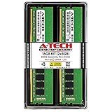
- Compatible with select DDR4 Desktop computers + Easy to install at home, no expertise required
- Maximize your system's performance, boost loading speeds and multitask with ease
- Backed by A-Tech's Lifetime Warranty + Friendly tech support team available to help before and after your purchase
- 16GB RAM Kit ( 2 x 8GB Modules ) | DDR4 DIMM 288-Pin | Speeds up to 2666MHz (2667MHz), PC4-21300 / PC4-2666V
- NON-ECC Unbuffered | 1Rx8 or 2Rx8 - Single or Dual Rank | JEDEC DDR4 standard 1.2V
Allow time for first-boot memory training
Some platforms repeatedly start and stop while the firmware calibrates memory. ASRock’s generic FAQ says that certain first boots can take three to five minutes because of memory training; that is an example, not a universal time for every DDR4 board. Consult the model-specific manual, leave the system undisturbed for the stated interval, and intervene only if the board’s instructions indicate a fault: ASRock’s debug FAQ.
Test DDR4 memory one module at a time
“DDR4” identifies the memory generation. It does not guarantee that every DDR4 kit works with every motherboard, CPU, capacity, speed, or DIMM population.
Reseat the DIMM
- Switch off the PSU, unplug AC power, and press the case power button briefly.
- Open both retention latches (or the latch specified by the board) and remove the DIMM.
- Align the notch in the module with the keyed ridge in the slot. DDR4 cannot be inserted correctly when the notch is misaligned; never force it.
- Press evenly on both ends until the latches close. A partially inserted module can produce a DRAM debug light or a blank display.
Use the recommended single-DIMM slot
Install one module in the slot named by the motherboard manual, commonly the second slot in a channel, but do not assume that layout. Test the first module alone, then the second module alone in that same recommended slot. If neither works, test the other slots in the sequence the manual specifies. This separates a bad DIMM from a bad slot or an unsupported population.
AMD and ASUS both recommend single-stick and slot testing and checking the board’s memory support information: AMD and ASUS.
Check the support list and population rules
Look up the exact motherboard model’s qualified-vendor list (often called a QVL), the supported capacities and speeds, and the recommended slot order. Also check the CPU’s memory specifications. A kit can be electrically functional yet fail to train when its speed, capacity, rank, or number of modules exceeds the board or CPU’s supported configuration.
Intel’s support guidance states: “The DRAM should also be compatible. Refer to your motherboard manufacturer’s site and the product specification page and the CPU to check memory compatibility.” Treat a replacement kit as a last step after single-module testing and compatibility checks point to the DIMM or configuration, not merely because the label says DDR4.
Rank #4

- Boosts System Performance:16GB DDR4 laptop memory RAM kit (2x8GB) that operates at 3200MHz to improve multitasking and system responsiveness for smoother performance
- Easy Installation: Upgrade your laptop RAM with ease—no computer skills required Follow step-by-step how-to guides available at Crucial for a smooth, worry-free installation
- Compatibility Guaranteed: Ensure seamless compatibility with your laptop by using the Crucial System Scanner or Crucial Upgrade Selector—get accurate recommendations for your specific device
- Trusted Micron Quality: Backed by 42 years of memory expertise, this DDR4 RAM is rigorously tested at both component and module levels, ensuring top performance and reliability
- ECC Type = Non-ECC, Form Factor = SODIMM, Pin Count = 260-pin, PC Speed = PC4-25600, Voltage = 1.2V, Rank and Configuration = 1Rx16, 1Rx8 or 2Rx8
Confirm CPU support and the BIOS version
A processor can fit the socket and still be unsupported by the motherboard’s installed BIOS. Check the board maker’s CPU support page using the exact motherboard revision and exact CPU model.
What’s actually slowing this PC down?
Pick the symptom - the matching free tool is one click away.
- Find the motherboard model and revision printed on the PCB or its box.
- Open the manufacturer’s CPU support list and locate the precise processor model.
- Record the minimum BIOS version listed for that CPU.
- Compare it with the BIOS version on the board, if it is printed on a sticker, shown in firmware, or available through a board diagnostic feature.
- If an update is required, use only the file and procedure for that exact board. A USB BIOS Flashback feature can update a board without a supported CPU only when that model explicitly provides it.
Socket and chipset names are not enough to establish support. AMD, Intel, ASUS, and MSI all direct builders to model-specific compatibility information; start with the board’s official CPU list and BIOS notes. Never interrupt power during an update, and do not use a file intended for another revision.
Reset firmware settings when settings may be wrong
An incorrect memory profile, overclock, or corrupted firmware setting can prevent startup even when the hardware is sound. Clear CMOS or load BIOS defaults using the motherboard manual.
- Shut down, switch off the PSU, unplug AC power, and press the case power button.
- Use the board’s documented clear-CMOS jumper, rear button, or battery-removal procedure. The location and timing are not universal.
- Restore power and attempt a start with the minimal configuration.
- After POST returns, re-enter firmware setup and leave memory and CPU settings at defaults until the system is stable.
AMD recommends a power flush or CMOS reset for relevant no-boot conditions. MSI specifies disconnecting PSU power before using its CMOS jumper or removing the battery: AMD’s procedure and MSI’s procedure.
When POST succeeds but the operating system does not load
If the machine consistently reaches the firmware menu, the core hardware has completed POST. The remaining problem is downstream: the firmware may not detect the intended drive, may be selecting the wrong boot device, or the OS installation may be damaged.
Outdated Drivers Are Slowing You Down
One free scan finds every outdated or missing driver and matches the right update for your exact hardware.Free scan · exact hardware matchWindows Errors? Fix Them Before They Spread
Repair common Windows errors and clear accumulated junk for a smoother, more stable PC - no reinstall needed.Free scan · no reinstall- Open the firmware storage or NVMe information page and check whether the OS drive is listed.
- Check the boot-order page and place the intended OS boot entry first. On UEFI systems this is usually a named boot manager rather than the raw drive model.
- If the drive is absent, power down and reseat its SATA data/power connectors or M.2 module according to the board manual. Test the board’s supported slot if the manual distinguishes shared lanes.
- If the drive is detected but the boot entry is missing or fails, use the OS installer or recovery environment for that operating system.
AMD distinguishes a system that fails POST from one that passes POST but fails OS loading; storage and OS repair belong to this latter branch: AMD’s boot-failure guide.
Use a symptom-based decision path
| Observed result after the check | Next action |
|---|---|
| No response after verified outlet, PSU switch, 24-pin, CPU power, GPU power, and front-panel wiring | Test with known-good compatible power hardware or contact the PSU/motherboard manufacturer; the available procedures do not identify a failed part by themselves. |
| Fans spin and VGA indicator stays on | Verify monitor input, cable, GPU seating and power, and whether the CPU has integrated graphics. Use the board manual’s LED definition. |
| DRAM indicator stays on or one DIMM fails alone | Reseat, test each module and slot, then compare the kit and population with the motherboard QVL and CPU specifications. |
| CPU indicator stays on or the CPU is absent from the support list | Check the required BIOS version and update only with the exact board procedure. |
| Minimal configuration reaches POST | Reconnect storage, USB devices, DIMMs, and PCIe cards one at a time until the failure returns. |
| Firmware sees the drive but does not boot it | Correct the boot order or repair the OS installation; this is no longer a basic POST failure. |
Common mistakes that create a false diagnosis
- Using the motherboard video port with a CPU that has no iGPU: the port cannot generate an image without processor graphics. Use the discrete card instead.
- Confusing CPU and PCIe power: the plugs are not interchangeable. Match each cable to the label and socket printed on the PSU and board.
- Installing two DIMMs in arbitrary slots: follow the board’s single- and dual-channel population diagram.
- Changing several things at once: a minimal build and one-change-at-a-time reconnection preserve the evidence about what fixed or caused the failure.
- Assuming a long first restart is a dead board: some boards train memory for several minutes on first startup, as ASRock notes. Follow the exact model’s guidance before interrupting it.
- Flashing an unrelated BIOS file: confirm the board model and revision, use the documented update method, and maintain stable power throughout.
- Buying RAM solely because the system is new: DDR4 compatibility depends on the board, CPU, kit and slot population. Test and verify first.
When to stop troubleshooting and request service
Contact the component manufacturer or system builder after you have documented the exact symptom, verified power wiring, tested the minimal configuration, tried the manual’s DIMM slots, checked CPU/BIOS support, and performed the board-approved CMOS reset. Include photos of cable connections, the board’s model and revision, the CPU and memory part numbers, the debug LED or POST code, and the result of each one-module test. That information lets support distinguish a configuration problem from a likely hardware fault without speculative part swapping.
Quick Recap
Product prices and availability are accurate as of the date/time indicated and are subject to change. Any price and availability information displayed on Amazon at the time of purchase will apply.

