
iTechGuides is reader-supported. When you buy through links on our site, we may earn an affiliate commission. As an Amazon Associate I earn from qualifying purchases. Learn more
To use the SH-C30L with an Arduino UNO, connect the UNO to an MCP2515 CAN module over SPI, then connect that module and the SH-C30L to the same CAN_H/CAN_L bus. The SH-C30L connects to the computer over USB; it does not connect to the UNO’s SPI pins. This setup lets the computer and Arduino exchange classic CAN frames.
How the parts work together
The UNO has no built-in CAN controller in this setup. The MCP2515 module supplies the CAN interface: the UNO sends and receives data through SPI, while the module’s CAN transceiver connects to the bus. The SH-C30L is the computer’s USB-to-CAN interface.
The signal path is:
Computer ⇄ USB ⇄ SH-C30L ⇄ CAN_H/CAN_L bus ⇄ MCP2515 module ⇄ SPI ⇄ Arduino UNO
Free tools Windows power users keep installed
One-click scans. No signup required.
DSD TECH specifies the SH-C30L for CAN 2.0A and 2.0B at up to 1 Mbps. It does not support CAN FD, according to the manufacturer’s firmware release notes. DSD TECH SH-C30L product page · DSD TECH firmware release notes
#1 Best Overall
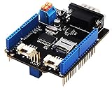
- 💎Notice: When we produced the new batch of CAN-BUS Shield V2, the wire of the back pads was embedded inside the PCB, although the wire between the pads is now not visible on the outside, the inside is still connected, if you want to change the wiring of the pads, you still need to cut the wiring in the PCB first.
- 💎CAN-BUS is a common industrial bus because of its long travel distance, medium communication speed and high reliability. It is commonly found on modern machine tools and as an automotive diagnostic bus. Thanks for CAN-BUS, makers are able to hack their cars more conveniently.
- 💎The CAN-BUS Shield V2 still uses MCP2515 as CAN-BUS controller and MCP2551 as CAN transceiver. OBD-II or CAN standard pinout can be selected by switching jumpers on DB9 interface, the default pinout is OBD-II.
- 💎We add a TF card slot for data storage and the CS pin can be either set to D4 or D5. The INT pin can also be set to D2 or D3 by switching jumpers on the back of the shield.
- 💎CAN BUS Shield Work well with Arduino UNO (ATmega328), Arduino Mega (ATmega1280/2560) as well as Arduino Leonardo (ATmega32U4) and LinkIt One.
What you need to check before wiring
- An Arduino UNO and an MCP2515 CAN module with a CAN transceiver. Check the module’s supply requirements, pin labels, termination jumper, and oscillator marking; modules may use different oscillator frequencies.
- An SH-C30L adapter and its CAN terminal block. DSD TECH lists a three-pin terminal block in the package, along with the adapter and manual.
- CAN wiring to connect the two CAN interfaces, with CAN_H matched to CAN_H and CAN_L to CAN_L. The practical setup also connects the grounds.
- A computer-side CAN application or compatible host interface. Firmware generation affects how the adapter is presented to the computer.
Wire the UNO to the MCP2515 module
For the cited UNO example, connect the module as follows. Confirm the labels on your particular breakout before applying power.
| MCP2515 module pin | Arduino UNO pin |
|---|---|
| VCC | 5V, if supported by the module |
| GND | GND |
| CS | D10 |
| MISO | D12 |
| MOSI | D11 |
| SCK | D13 |
| INT | Not connected in the cited example; use it only if required by your sketch and module setup |
The SPI pin assignments and D10 chip-select are for this UNO example. If you change the chip-select wiring, make the sketch use the same pin. Another Arduino board may use different SPI pins.
Connect the CAN bus and set termination
Connect the MCP2515 module’s CAN_H to the SH-C30L’s CAN_H, and CAN_L to CAN_L. Do not cross the two signals. Connect ground between the Arduino-side hardware and adapter for this bench setup. The arrangement is bidirectional: frames from the UNO can reach the computer, and frames sent from the computer can reach the UNO.
Do these 3 things before closing this tab:
1Clear out junk files and repair common Windows errors2Scan for outdated or missing drivers - takes under a minute3Repair Windows errors before they cause bigger problemsRank #2

- The information below is per-pack only
- 💎Notice: When we produced the new batch of CAN-BUS Shield V2, the wire of the back pads was embedded inside the PCB, although the wire between the pads is now not visible on the outside, the inside is still connected, if you want to change the wiring of the pads, you still need to cut the wiring in the PCB first.
- 💎CAN-BUS is a common industrial bus because of its long travel distance, medium communication speed and high reliability. It is commonly found on modern machine tools and as an automotive diagnostic bus. Thanks for CAN-BUS, makers are able to hack their cars more conveniently.
- 💎The CAN-BUS Shield V2 still uses MCP2515 as CAN-BUS controller and MCP2551 as CAN transceiver. OBD-II or CAN standard pinout can be selected by switching jumpers on DB9 interface, the default pinout is OBD-II.
- 💎We add a TF card slot for data storage and the CS pin can be either set to D4 or D5. The INT pin can also be set to D2 or D3 by switching jumpers on the back of the shield.
Two-node bench bus
If the SH-C30L and MCP2515 module are at opposite ends of a short, two-node bus, enable 120 Ω termination at each end if the relevant switch or jumper is provided. With power removed, two 120 Ω resistors in parallel should measure about 60 Ω across CAN_H and CAN_L. This is a wiring check, not a powered measurement.
Bus with more than two nodes
Terminate only the two physical ends of the bus. Do not enable a termination resistor at every node. The SH-C30L has switchable 120 Ω termination; check the MCP2515 board for its own termination jumper.
Match the CAN bitrate and MCP2515 oscillator
Both CAN endpoints must use the same bitrate. The Arduino Project Hub example initializes the MCP2515 at 500 kbps with an 8 MHz oscillator, but that 8 MHz value describes the author’s module, not every MCP2515 board. The SH-C30L’s specified ceiling is 1 Mbps; select a bitrate supported by both endpoints.
Rank #3

- 2PCS CAN-BUS Shield MCP2515
Read the oscillator marking on your module and configure the library to match it. The autowp MCP2515 library documents a 16 MHz default clock, so leaving that default unchanged on an 8 MHz module can prevent reliable communication. The two examples use different library APIs; do not combine their code without adapting it to the library actually installed.
The Arduino Project Hub example uses the mcp_can library and declares MCP_CAN CAN0(10), matching chip-select D10. See the Arduino Project Hub example and the autowp MCP2515 library documentation for their respective configuration details.
Set up the computer-side interface
DSD TECH lists Candlelight, SocketCAN support, Cangaroo, BUSMASTER, and a cross-platform Python library among the SH-C30L software options. The host setup depends on the adapter’s firmware and operating system, so do not assume one driver procedure applies to every unit.
Rank #4
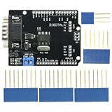
- DIY KIT MCP2515 EF02037 CAN BUS Shield Controller Board Communication Speed High CAN Module For Arduino
- Implements CAN V2.0B at up to 1 Mb/s
- SPI Interface up to 10 MHz
- Standard (11 bit) and extended (29 bit) data and remote frames Industrial standard 9 pin sub-D connector
- Two receive buffers with prioritized message storage Operating voltage: DC5-12V
The manufacturer’s release notes say the v2.1 SH-C30 family build uses the raw USB candleLight interface, with gs_usb on Linux and WinUSB on Windows. The vendor also advises identifying firmware versions by the USB-reported device name. Older units may have earlier firmware builds. Check the vendor’s current support files and match the host software to the device’s reported interface. Firmware reflashing is not required for ordinary use, according to the release notes.
Troubleshoot in a useful order
- Check USB recognition. Confirm the computer detects the SH-C30L and note the USB-reported device or firmware identity. Resolve host-interface recognition before debugging CAN traffic.
- Inspect the bus wiring. Confirm CAN_H goes to CAN_H, CAN_L to CAN_L, and the bench setup’s grounds are connected.
- Match communication settings. Set both CAN endpoints to the same bitrate, and make the MCP2515 library’s clock setting match the crystal on the actual module.
- Verify UNO SPI and chip-select. Check the UNO’s SPI pins and confirm the CS wire matches the pin declared in the sketch.
- Check termination with power off. For the two-ended bench bus, measure across CAN_H and CAN_L; about 60 Ω is expected when both 120 Ω end resistors are enabled.
- Keep fault categories separate. A computer that does not recognize the adapter points to a USB, firmware, or host-software issue; recognized hardware with no CAN traffic calls for checking wiring, bitrate, oscillator configuration, termination, and sketch/library settings.
Sources and scope
The product specifications and firmware behavior above are based on DSD TECH’s SH-C30L product page and firmware release notes. The wiring and termination guidance follows the Play with Circuit SH-C30L and UNO guide. Library and example details are linked in the relevant sections; the Arduino configuration is specific to that contributor’s hardware.
What’s actually slowing this PC down?
Pick the symptom - the matching free tool is one click away.
Quick Recap
Product prices and availability are accurate as of the date/time indicated and are subject to change. Any price and availability information displayed on Amazon at the time of purchase will apply.

