
iTechGuides is reader-supported. When you buy through links on our site, we may earn an affiliate commission. As an Amazon Associate I earn from qualifying purchases. Learn more
For a light camera that only needs a bounded pan and tilt angle, start with a positional servo. It accepts a target through PWM and uses an internal position sensor to correct error, so you can get a working mount with relatively little control software. Choose a stepper motor and a current-regulating driver when the payload is heavier, the axis must rotate continuously or through a wide angle, or you need strong, repeatable low-speed holding. Add an encoder, home sensor, or stall-detection method whenever an unnoticed lost step would point the camera incorrectly.
The motor alone does not determine whether a mount will work. Torque at the required speed, camera inertia, balance, travel limits, backlash, heat, power, noise, controller complexity, and duty cycle all matter. The procedure below turns those requirements into a defensible motor choice.
The practical decision
A servo and a stepper are not simply two versions of the same actuator. A conventional positional servo is a complete local feedback system: its controller compares the commanded angle with the angle reported by an internal potentiometer or encoder, then drives the motor to reduce the error. A conventional stepper receives pulses and advances by commanded increments; unless you add feedback, the controller assumes every increment occurred.
Use a positional servo when most of these statements describe your mount:
#1 Best Overall

- Good performance digital standard Deegoo-FPV servo, which can be a common use for robots, mechanical arms, climbing cars and remote control toys
- This high-speed standard servo motor can rotate 180 degrees (90 in each direction)
- Stall Torque: 6V, 13 kg·cm; No-load Speed: 4.8V: 0.17 s/60°, 6V: 0.13 s/60°; Operating Conditions: 5V, 2A; 5V, 1A; 6V, 1A
- Connector wire length 300mm. Stable and shock proof double coreless motor, metal gear, ball bearing design,Through external adapter
- This servo offers a full range of 180° with metal gears. Application:RC robot, airplane control, robot arm and boats. Fit for all kind of R/C toys and experiments
- The camera is light enough for the selected servo’s torque at the required speed.
- Pan and tilt are bounded, such as a tilt range of less than one revolution and a pan range limited by a bracket or cable.
- You want the shortest path from a microcontroller PWM output to a working prototype.
- Small position errors caused by an overload should be corrected automatically within the servo’s mechanical limits.
Use a stepper when these conditions dominate:
- The axis needs many turns or continuous rotation.
- The camera and bracket create substantial inertia or require strong energized holding at zero speed.
- You already have step/dir motion-control hardware or need repeatable, very slow motion.
- You can provide a properly sized current-regulating driver, power supply, thermal path, and a way to establish or verify position.
Neither choice guarantees accuracy at the lens. A flexible bracket, gear backlash, shaft compliance, or cable drag can move the camera even when the motor shaft is at its commanded angle.
How each motor controls position
Positional servo: a local closed loop
The command is commonly a PWM signal whose pulse width represents a target angle. The servo’s electronics read its internal position sensor, calculate the difference between target and measured position, and energize the motor in the direction that reduces that difference. This is the feedback-loop principle described by Festo: an encoder or similar sensor monitors position so the drive can adjust movement toward the requested location.
The loop can correct a load disturbance while the actuator remains within its travel, current, and thermal limits. It does not know the camera’s optical line of sight, bracket flex, or backlash outside the servo’s own sensor. A servo that reports its output gear at 90 degrees can still leave the camera a little off if the mount twists.
Stepper: commanded increments with optional feedback
A stepper’s driver energizes its phases in a sequence. A full-step motor may have a few hundred commanded positions per revolution; Festo gives 200–400 steps per revolution as a typical range for common models. Microstepping divides those electrical positions into smaller command increments and can reduce vibration, but it does not guarantee proportional real-world accuracy under load.
When the windings remain energized, a stepper can produce strong holding torque at zero speed. AMCI describes this as holding a load against an external force while the rotor is stationary, and Oriental Motor identifies zero-speed holding torque as a stepper advantage. Torque falls as speed rises, so the relevant value is the torque on the motor’s torque-speed curve at your actual acceleration and slew speed, not the headline holding number.
In an open-loop installation, an overload can make the rotor fall behind without an alarm. An encoder on the shaft, a home or limit sensor, or a driver with sensorless stall detection can provide a recovery or fault strategy. TI’s video-surveillance guidance specifically uses higher-torque steppers and drivers for camera pan and tilt and calls out current sensing, microstepping, and sensorless stall detection as useful options.
Rank #2

- MG90S Micro Servo Motor, upgraded SG90 high torque servo.
- Stall Torque: 2.0kg/cm(6.0V). Operating Speed: 0.08 seconds/60 degrees (6.0V).
- Operating Voltage: 4.8V–6V. A stable 5V power supply is recommended for smooth and reliable performance.
- Metal Gear: Aluminum metal teeth, coreless motor, high precision, 180° rotation. Metal Gear with less noise for added strength and durability.
- Tiny and lightweight with high output, this mini small micro servo is compatible with arduino, Ideal for raspberry pi,drone, airplanes, RC crawler, robot arm, quadcopters, rc boat, DIY project. For multi-servo setups, an external stable power supply is recommended.
Servo-versus-stepper comparison
| Decision axis | Positional servo | Stepper |
|---|---|---|
| Position feedback | Internal potentiometer or encoder closes the local loop and corrects load error within the actuator’s limits. | Conventional control is open loop; an encoder or stall detection must be added for feedback. |
| Travel | Convenient for bounded angles; the actual range depends on the servo design and its mechanical stops. | Naturally suited to multi-turn or continuous rotation, provided cables and hard stops are managed. |
| Holding | The controller actively maintains the target; current and heat rise with load. | Strong energized holding torque at zero speed; the windings still consume power unless a brake or another support mechanism carries the load. |
| Torque and speed | Useful torque over a broad operating range, with peak torque available for acceleration and changing loads. | High at standstill and low speed, declining as speed increases; size from the torque-speed data. |
| Overload behavior | Feedback can detect and correct position error while current, travel, and temperature limits are respected. | Can miss steps silently without an encoder or stall-detection strategy. |
| Electronics | PWM command and a supply rated for the servo’s stall current are normally sufficient. | Requires a current-regulating driver, step/dir or equivalent control, and a supply sized for phase current; microstepping can reduce vibration. |
| Cost and complexity | Small hobby units integrate motor, gears, sensor, and controller; industrial servos add encoder and drive cost. | The motor can be inexpensive, but the driver, power supply, gearing, sensors, and thermal design add to the system. |
| Typical fit | Light payload, bounded angle, rapid prototype, and simple controller. | Heavier payload, wide or continuous travel, low-speed holding, or an existing step/dir motion system. |
Size the actuator from the camera and mechanism
Do not select a motor from camera mass alone. The critical quantity on a tilt axis is gravitational torque, which grows with the perpendicular distance from the axis to the combined center of mass. A balanced camera can require little steady torque even if it is heavy; an unbalanced camera can overload a small actuator quickly.
Quick wins for a faster PC:
Clear out junk files and repair common Windows errorsFree Scan →Fix the driver behind crashes, sound loss and screen glitchesFind Drivers →Repair Windows errors before they cause bigger problemsFix Now →1. Measure the complete moving assembly
- Record camera mass, lens mass, bracket mass, and the mass of any quick-release plate that moves with the axis.
- Measure the center-of-mass offset from the pan and tilt axes. Use the worst orientation, not the convenient bench position.
- Estimate cable drag, bearing friction, seal friction, and any force from a moving cable loop.
- Note whether the axis is balanced by a counterweight, spring, gas strut, or counter-torque from a gearbox.
2. Calculate the worst static torque
For a simple unbalanced tilt axis, gravitational torque is approximately Tg = m × g × r, where m is the moving mass in kilograms, g is 9.81 m/s², and r is the perpendicular center-of-mass distance in meters. Add friction torque and the torque needed to accelerate the rotating assembly. If several masses sit at different radii, calculate each contribution and add them.
Acceleration torque depends on rotational inertia and angular acceleration: Ta = J × α. A long lens or camera cage can have much more inertia than its mass suggests. Pan motion often has lower gravitational torque than tilt but can demand significant acceleration torque when the camera is offset from the vertical axis.
3. Define the motion requirement
- Maximum slew speed in degrees per second or revolutions per minute.
- Acceleration and the required settling time after a command.
- Allowed pointing error at the camera, including backlash and structural flex.
- Pan and tilt travel, including whether a full or multiple revolution is required.
- Duty cycle: brief repositioning, repeated scans, or continuous operation.
4. Select from torque-at-speed data
Choose a motor whose available torque at the required speed exceeds the worst calculated load with practical margin. A servo’s stall rating is not a continuous rating, and a stepper’s zero-speed holding rating does not describe its high-speed capability. The margin must also cover cable drag, friction changes, manufacturing tolerance, and acceleration.
5. Consider reduction and balancing
A belt or gearbox can multiply output torque and improve angular resolution, but it introduces inertia, friction, and possibly backlash. Reduction can also let a stepper operate in a more favorable portion of its torque-speed curve. A balanced tilt axis reduces the continuous torque and heat that either motor must supply. Specify the backlash at the camera output, not only the motor shaft.
What’s actually slowing this PC down?
Pick the symptom - the matching free tool is one click away.
Servo-specific design checks
Verify the command and electrical limits
Arducam’s servo-steer PTZ documentation lists 50 Hz PWM control as an example. Treat that as a specification for that configuration, not a universal rule: verify the selected servo’s accepted pulse range, update rate, direction, neutral position, travel limits, supply voltage, and stall current. A microcontroller signal must share a suitable ground with the servo supply, while the supply itself must handle the current surge when the gear train starts or stalls.
Rank #3
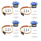
- SG90 9G micro digital servo motor made from high-quality plastic and featuring a gear medium, this servo motor is durable and reliable, ensuring that it provides long-lasting performance even after multiple uses
- SG90 9g micro digital servo motor servo motor can operate within a voltage range of 4.2-6V, making it compatible with a wide range of power sources
- SG90 9G micro servo motor with a torque of 1.6KG/CM (at 4.8V) and a response speed of 0.3s/60 degrees, this servo motor provides high performance and fast response times
- SG90 9G servo motor features a small size and lightweight design, making it ideal for use in a wide range of electronic projects
- This sg90 servo motor is suitable for use in a wide range of electronic diy projects, including 450 fixed-wing and helicopter models, as well as other robotics applications
The Arducam documentation also gives a servo example rated at 15 kg/cm stall torque at 4.8–7.2 V. That is a stall figure for the cited example and voltage range, not a promise that a 15 kg/cm servo can safely move every camera. Convert the rating to the output geometry you actually use, and check the manufacturer’s speed, duty-cycle, temperature, and continuous-load limits.
Account for deadband, backlash, and heat
Small servos may stop correcting inside a deadband, while inexpensive gear trains can have measurable backlash. A camera can therefore oscillate around a target or settle with a repeatable offset. Reduce imbalance, use a rigid bracket, and tune command updates rather than forcing rapid alternating corrections. Holding an unbalanced camera continuously keeps the motor energized and generates heat; provide ventilation and avoid treating a short-duration stall rating as continuous capacity.
Set safe travel limits
Use software limits inside the servo’s specified travel and add mechanical stops that cannot crush the gears or cable. On startup, move cautiously to a known reference if the application permits it. Never assume that the PWM neutral value corresponds to the exact mechanical center after a servo horn has been installed.
Recommended Free Tools
Stepper-specific design checks
Choose the motor and driver together
The driver must regulate phase current to the motor’s rating and protect against over-temperature and over-current conditions. Select a supply that leaves the driver enough voltage headroom at the desired speed, then confirm wiring, phase inductance, current limit, and cooling. Microstepping can make pan or tilt motion quieter and smoother, but the controller must generate the corresponding pulse count and the available incremental torque still depends on load and resonance.
Use a realistic torque-speed curve
At standstill, an energized stepper can hold a load strongly; as speed rises, winding inductance and back electromotive force reduce available torque. Acceleration that is too abrupt can cause a step loss even when the final running speed appears acceptable. Use an acceleration ramp, test the worst camera orientation, and leave margin above the calculated torque rather than operating at the curve’s edge.
Plan for position after power-up
A conventional stepper does not know its absolute shaft position after power is removed. Establish a home reference with a limit switch, optical or magnetic sensor, mechanical datum, or absolute encoder. If the mount must retain absolute pointing through a restart, use an encoder or another absolute reference rather than assuming the last commanded step count survived.
Rank #4

- SG90 9G digital Servo - Miuzei 9g servo motor for remote control helicopters, micro robot, robot arm and boats. Fit for ALL kinds of R/C car and also make electronics DIY compatible with Arduino, Raspberry Pi.
- Mini Servo - small servo motor compatible with JR and Futaba interface. Micro servo running speed (at no load) : 0.09 sec/60° (4.8V) 0.08 sec/60°(6V). Running angle: 180 degree.
- Micro Servo Motor - Stall Torque (4.8V): 19.6 oz /in (1.4kg/cm). Dead band width: 5 usec. Operating Voltage: 4.8V-6.0V.
- Application Fields -Servos used for drone, DIY project, RC crawler, helicopterfixed-wing, helicopter, KT, glider, small robot, robotic arm and other models.
- Note - Starting current of the analog servo motor should be over 1A and servo sg90 are analog servos need to continuously provide a PMW signal, then it will be work normally.
Provide cable management and hard stops
Continuous pan can twist a cable bundle until it damages a connector or pulls the camera. Define a permitted rotation range, add a cable loop or slip-ring solution appropriate to the design, and put hard stops outside the normal software limits. A home sensor should be reachable without driving the mechanism into a damaging stop.
Crashes, No Sound, or Screen Glitches?
Random freezes, missing sound and display glitches usually trace back to one bad driver. Find and replace yours safely.Free scan · under a minuteWindows Errors? Fix Them Before They Spread
Repair common Windows errors and clear accumulated junk for a smoother, more stable PC - no reinstall needed.Free scan · no reinstallFeedback, accuracy, and camera pointing
A servo’s internal sensor closes only the motor’s local loop. A stepper encoder likewise reports the shaft or gearbox location unless it is mounted at the camera output. In both designs, the final line of sight can be wrong because of bracket deflection, bearing play, gear backlash, or a shifting center of mass when a zoom lens extends.
Use the simplest feedback that meets the risk:
- For a light, bounded-angle hobby mount, the servo’s internal feedback plus conservative mechanical stops may be sufficient.
- For a stepper that must recover from a missed step, add a shaft encoder, output-side encoder, or a driver with sensorless stall detection and a defined fault response.
- For absolute pointing after power loss, add an absolute encoder or a repeatable homing datum.
- For demanding optical accuracy, calibrate the camera output against a target and measure backlash in both directions.
Power, heat, noise, and control complexity
Servo and stepper systems spend power differently. A servo draws more current when correcting a large error or holding an unbalanced load; a stepper can draw near its set phase current while stationary and energized. Reducing current at rest may lower heat, but it also lowers holding torque and can allow the camera to move. A brake, counterbalance, or mechanical lock can carry the load when electrical holding is unnecessary.
Steppers can produce audible tone and mechanical resonance, especially at low step rates or poorly tuned acceleration. Microstepping, a rigid mount, belt reduction, and a suitable acceleration profile can reduce vibration. Servos can be quiet at light load but may buzz as the feedback loop corrects around a deadband or backlash. Neither noise level nor lifetime has a universal servo-versus-stepper number; those outcomes depend on the motor, gearbox, driver, payload, balance, and duty cycle.
Budget the complete system rather than the motor price: driver, supply, brackets, coupling, bearings, encoder or home sensors, heat sinking, wiring, and mechanical protection can dominate a small prototype.
Two implementation paths
Bounded-angle servo mount
- Balance the camera about each axis and measure the worst gravitational torque.
- Select a metal-gear positional servo whose torque, speed, travel, voltage, and stall-current specifications meet that load with margin.
- Design the bracket with hard stops, a rigid output bearing, and a cable route that cannot pull on the horn.
- Power the servo from a supply sized for stall and startup current; do not rely on a microcontroller board’s small regulator unless its rating explicitly covers the load.
- Generate the servo’s specified PWM signal, begin at a conservative center position, and verify direction before attaching the camera.
- Command small angle changes, measure settling and heat, then expand the travel while checking that no stop or cable is reached.
- Record the camera’s actual pointing error in both directions so backlash and bracket flex are included in the operating limits.
Wide-angle or heavy stepper mount
- Calculate gravitational, friction, and acceleration torque and select a motor from its torque-speed curve at the planned slew rate.
- Choose a current-regulating driver with the motor’s phase-current range, thermal protection, and the desired microstepping and stall-detection features.
- Provide a supply with adequate voltage and current, short protected wiring, and a heat path for the driver and motor.
- Implement an acceleration ramp; begin with a low speed and verify that the rotor does not stall in the worst camera orientation.
- Install a home sensor or absolute reference and define what the controller does after a stall, reset, or emergency stop.
- Set software limits inside mechanical hard stops and route cables for the permitted number of revolutions.
- Test repeated reversals, long holds, and the full duty cycle while monitoring motor and driver temperature.
Worked sizing examples
Why balance changes a tilt decision
Suppose a 1.2 kg camera-and-bracket assembly has its center of mass 0.08 m from the tilt axis. The worst gravitational torque is approximately 1.2 × 9.81 × 0.08 = 0.94 N·m before friction and acceleration. If a counterbalance reduces the offset to 0.01 m, the corresponding gravitational term falls to about 0.12 N·m. The same camera can therefore require dramatically different actuator capacity depending on bracket geometry. The calculation still needs an allowance for acceleration, cable drag, and a safety margin.
Best Value
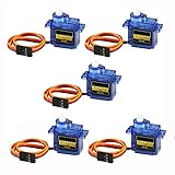
- 100% NEW brand,high quality. Stall Torque (4.8V): 17.5oz /in (1kg/cm); Operating voltage: 3.0V~ 6V; Temperature range: -30 to +60; Dead band width: 7usec
- Mini servo SG90 is tiny and lightweight with high output power
- SG90 servo motor compatible with the project like Robot Arm/ Robot hand/ control the servo with potentiometer/ multi servo control
- The SG90 has 3 wire interfaces in which the connections should be made as follows: Red wire-5V, Brown Wire-Ground, Yellow wire-digital pin 9
- SG90 9G micro servo motor for remote control helicopters, micro robot, robot arm and boats
Why step angle is not the same as camera accuracy
An Arducam PTZ stepper configuration lists a 0.224° step angle. That figure describes one motor step in that configuration. A reduction drive can make the output increment smaller, while backlash, structural flex, missed steps, and center-of-mass torque can make the camera’s repeatable pointing error larger. Conversely, a servo’s internal sensor can correct motor position but cannot remove output backlash. Evaluate the complete axis at the lens, not just the motor’s nominal increment.
Common failure modes and fixes
The camera droops when stopped
On a servo, the load may exceed continuous holding capability or the supply may sag during correction. Rebalance the axis, reduce the center-of-mass offset, verify stall-current capacity, and check temperature. On a stepper, the selected holding torque may be insufficient or current may be set too low; verify phase current and use a brake or counterbalance if the axis must hold without heat.
The stepper loses position during a sweep
Reduce acceleration and speed, increase torque margin, improve supply voltage within the driver’s limits, reduce friction, and check for resonance. Add an encoder or sensorless stall detection if a missed step cannot be tolerated, then define a homing or shutdown response.
Do these 3 things before closing this tab:
1Fix the driver behind crashes, sound loss and screen glitches2Clear out junk files and repair common Windows errors3Scan for outdated or missing drivers - takes under a minuteThe servo jitters or buzzes
Check that PWM timing and pulse limits match the servo, that the supply is clean and adequately sized, and that the horn is not binding a mechanical stop. Reduce imbalance and avoid commanding tiny alternating corrections inside the mechanism’s backlash or deadband.
The mount points differently after reboot
A stepper’s step count is not an absolute reference after power loss. Home the axis or use an absolute encoder. A servo may return to its commanded local angle while the camera remains offset because the horn was reinstalled, a gearbox has backlash, or the bracket shifted; include a repeatable datum and recalibration procedure.
The axis works briefly and then overheats
Measure motor and driver temperature over the real duty cycle, not only during a short demonstration. Reduce continuous holding current, rebalance the load, improve cooling, lower duty cycle, or add a mechanical support. Do not infer continuous safety from a stall or holding specification.
Decision checklist
- Is the required pan or tilt travel bounded, or must the axis turn continuously?
- What are the worst gravitational and acceleration torques at the actual center of mass?
- What torque is available at the required speed and temperature, rather than only at stall or zero speed?
- How much backlash, flex, and pointing error can the camera tolerate?
- What happens after overload, power loss, reset, or a cable snag?
- Can the supply, driver, wiring, and thermal design handle stall or continuous holding current?
- Are home sensors, hard stops, and cable management included in the mechanical design?
- Would a counterbalance or reduction make either motor smaller, cooler, or more accurate?
For a bounded-angle light camera, a correctly sized positional servo is usually the fastest reliable solution. For a heavy camera, continuous pan, strong low-speed holding, or an existing step/dir architecture, a stepper with a current-regulating driver is often the better foundation. Add external position verification whenever a silent overload would create an unacceptable view.
Free tools Windows power users keep installed
One-click scans. No signup required.
Quick Recap
Product prices and availability are accurate as of the date/time indicated and are subject to change. Any price and availability information displayed on Amazon at the time of purchase will apply.

