
What’s actually slowing this PC down?
Pick the symptom - the matching free tool is one click away.
iTechGuides is reader-supported. When you buy through links on our site, we may earn an affiliate commission. As an Amazon Associate I earn from qualifying purchases. Learn more
There is no universally best tactile-sensor technology. Choose an optical waveguide when electromagnetic-interference (EMI) immunity, electrical isolation, distributed measurement, or very fine spatial resolution justifies specialized optical hardware. Choose a capacitive sensor for a thin, flexible array when you can provide stable capacitance readout, shielding, and environmental compensation. Choose a resistive sensor or force-sensitive resistor (FSR) when low cost, simple electronics, and a fast prototype matter most.
The right comparison is therefore application-specific. A sensor that wins on laboratory resolution may be the wrong choice for a low-cost robot hand, while a simple resistive pad that detects contact reliably may be more useful than a complex device that measures force precisely but is difficult to package.
Quick comparison
| Criterion | Optical waveguide or fiber | Capacitive | Resistive |
|---|---|---|---|
| Best reason to choose it | EMI immunity, electrical isolation, distributed or very high-resolution sensing | Thin flexible arrays with compact electronics | Lowest-cost, quickest route to contact or pressure detection |
| How force is detected | Deformation changes transmitted light intensity, wavelength, interference, or scattering | Force changes electrode spacing, dielectric thickness, or dielectric constant | Force changes the resistance of a pressure-sensitive material or contact |
| Noise behavior | Unaffected by electromagnetic pickup in the sensing element; optical electronics still need good design | Small capacitance changes require shielding, grounding, and compensation | Wiring and analog electronics can pick up electrical noise |
| Potential resolution | Very high, depending on the optical architecture and interrogation method | High in well-designed microstructured arrays | Ranges widely with material, geometry, and conditioning circuit |
| Hardware burden | Light source, couplers, photodetector, and demodulation; packaging can be cumbersome | Capacitance-measurement front end, multiplexing, shielding, and calibration | Simple resistance measurement and inexpensive conditioning |
| Prototype cost and effort | Highest for most teams | Moderate | Lowest barrier for many experiments |
| Typical fit | Motor-rich robots, harsh or electrically isolated tools, distributed tactile skins | Wearables, flexible robotic skins, compact multi-pixel arrays | Exploratory robot hands, large-area contact pads, budget prototypes |
These are technology-level tendencies, not guaranteed specifications. Published devices within each category differ substantially in force range, hysteresis, drift, temperature response, lifetime, and sampling rate.
Recommended Free Tools
How the three sensor classes work
Optical waveguide and fiber sensors
An optical tactile sensor sends light through a waveguide, fiber, or deformable optical structure. Mechanical loading changes the optical path. The readout can track a change in intensity, wavelength, interference, or a scattered-light pattern. Silica fiber, polymer optical fiber, hydrogel structures, and micro- or nanofibers are all used in published designs.
#1 Best Overall
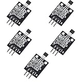
- Hall Switch Integrated Circuit Using hall Effect Principle
- Uses The Semiconductor Integrated Technology Manufacturing Magnetic Susceptibility of the Circuit
- Its Input For the Magnetic Induction Intensity, the Output is a Digital Voltage Signal
Fiber-optic tactile work is often grouped into four architectures: fiber Bragg grating (FBG), micro/nanofiber, specklegram, and Fabry–Perot sensors. An FBG reflects a wavelength that shifts as the grating is strained. A specklegram system interprets changes in the granular pattern produced by multimode propagation. Fabry–Perot devices measure changes in an optical cavity, and micro/nanofiber designs exploit strong interaction between deformation and the guided field.
The sensing element itself is dielectric, so it does not form an electrical antenna in the way a long metal trace does. That is the basis of the strong EMI immunity and electrical isolation often cited for photonic tactile sensing. The system is not automatically simple: a practical instrument still needs a stable LED or laser, optical coupling, a photodetector, and a method to demodulate the chosen signal.
Capacitive sensors
A capacitive tactile cell uses electrodes separated by a dielectric. Applied force changes the electrode spacing, the dielectric thickness, the dielectric constant, or a combination of these. The resulting capacitance change is measured by an electronic front end.
Capacitive layouts can be made thin and flexible, and electrodes can be arranged into compact matrices. Their main engineering challenge is that the useful change may be small compared with parasitic capacitance from traces, connectors, neighboring cells, the enclosure, or a nearby human hand. Stable excitation, guarding or shielding, careful grounding, and compensation for temperature and humidity are often necessary for repeatable results.
Resistive sensors and FSRs
A resistive tactile cell changes resistance when pressure-sensitive material is compressed, when conductive particles move closer together, or when two conductive layers make a pressure-dependent contact. A voltage divider, current source, or resistance-to-digital converter can read the result.
Resistive construction is attractive because the electrical circuit is straightforward and inexpensive. Films, conductive elastomers, printed materials, and commercial FSR elements can be cut or arranged over large areas. The trade-off is that resistance often depends on loading history, temperature, contact area, and material aging, so a low-cost prototype should not be assumed to be a precision force transducer.
Rank #2
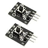
- Model: KY-004.Rating: 50mA 12VDC.
- Contact Resistance : 50mOhm max(initial). Package Included:2PCS.
- Key switch module and a digital interface, built-in 13 LED build a simple circuit to produce key warning lamp.
- This module is ideally suited to adding a button to your projects and will output a high signal when pressed.
- Good for use just anywhere on your project and great for debugging a project.
Where each technology wins
EMI immunity and electrical isolation
Optical waveguides have the clearest advantage near strong motors, inverters, transformers, radio transmitters, and high-current wiring. The sensing path carries light rather than an electrical signal, so electromagnetic pickup at the point of contact is greatly reduced. This is especially valuable when the tactile skin must be electrically isolated from a high-voltage tool or when a long cable runs through a noisy robot arm.
Capacitive systems can work in noisy machines, but they generally need deliberate shielding, controlled cable routing, driven guards, and compensation for changing parasitic capacitance. Resistive sensors can also be made robust, yet their analog wiring remains susceptible to interference and ground-potential problems. The severity depends on cable length, sampling circuit, filtering, and mechanical layout rather than on the sensor material alone.
Sensitivity and spatial resolution
Optical architectures can provide high sensitivity and fine spatial resolution, particularly when many sensing points are encoded along a fiber or when an optical image or speckle pattern is analyzed. The exact result depends on fiber type, coupling stability, mechanical transducer geometry, optical power, detector noise, and the demodulation algorithm.
Capacitive arrays can also reach high sensitivity. Microstructured dielectrics and small electrode gaps increase the fractional capacitance change, but they also make the design more sensitive to contamination, assembly tolerances, and parasitics.
Resistive devices cover a very broad range. A compliant, highly conductive composite may respond strongly at low pressure, while a thicker or harder stack may tolerate much higher loads with lower gain. The class label alone cannot predict resolution.
Force range, hysteresis, and drift
Force range is set by the mechanical stack before it is set by the readout. A soft elastomer gives low-force sensitivity but can saturate early. A stiff cover spreads load and extends range while reducing local deformation. Preload, cell size, layer thickness, and the shape of a raised or recessed feature all affect the result.
Rank #3

- DC 0~25V Voltage Detection Module Sensor
- Voltage input range: DC0-25 V
- Voltage detection range: DC0.02445 V-25 V
- Voltage analog resolution: 0.00489 V
- DC input interface: red terminal positive with VCC, negative with GND
Hysteresis is common in viscoelastic polymers and porous structures. The output during unloading may not follow the loading curve, and repeated cycles can shift the baseline. Optical sensors are not immune: the optical element may be stable while its elastomeric packaging creeps. Capacitive devices can drift as dielectric moisture changes, and resistive films can show resistance history and permanent set.
Response time
Photodetectors and electrical front ends can respond quickly, but the mechanical cover, adhesive, and elastomer usually dominate the tactile response. Capacitive and resistive electronics can also sample rapidly; the practical limit is commonly the mechanical relaxation time, filtering, and matrix scan rate.
A published example illustrates why individual results must not be generalized. A templated laser-induced-graphene resistive sensor was reported at 52,260.2 kPa−1 over 0–7 kPa, with a stated detection range up to 1,000 kPa and 12/46 ms response/recovery. That is one device under its reported test conditions, not an average for all resistive sensors or a direct comparison with every optical or capacitive design.
Fabrication, integration, and cost
Resistive sensors usually reach a working proof of concept with the fewest specialized parts: a sensing film or FSR, a resistor network, an analog input, and software calibration. They are therefore a sensible first build when the goal is contact detection, grasp-state feedback, or a rough pressure map.
Capacitive arrays require more attention to electrode patterning and readout. A multiplexed array can reduce wiring, but the scanner must settle quickly and reject crosstalk. Flexible substrates and printed electrodes simplify conformal packaging, while the electronics become the main integration task.
Optical systems add the most integration work. Coupling losses, connector alignment, bend radius, optical power budget, detector linearity, and demodulation all matter. Packaging must transfer force to the waveguide predictably without introducing unwanted bends or delamination. The extra effort is justified when electrical isolation or EMI performance has operational value, not merely because optical technology sounds more advanced.
Rank #4
![Arduino Modulino Buttons [ABX00110] - Qwiic-Compatible 3-Button Module with LEDs for Arduino Projects and Interactive Controls](https://m.media-amazon.com/images/I/51RRscDKihL._SL160_.jpg)
- Multiple Input Points: Features four distinct tactile buttons on a single module for multi-state or multi-function user input.
- Simplified Wiring: Uses an internal resistor ladder to read all four buttons through a single analog input pin, saving digital pins.
- User Interface Ready: Ideal for building menu navigation, game controllers, or simple control panels on prototypes.
- Plug-and-Play Integration: Designed as an easy-to-use module that quickly connects and interfaces with the Arduino ecosystem.
- Efficient Prototyping: Offers a compact and robust solution for adding essential digital input without breadboarding multiple components.
Which sensor is best for common projects?
Robot hand near motors or power electronics
Start with an optical waveguide if motor commutation, pulse-width-modulated drives, or high-current cables corrupt electrical measurements. Optical sensing is also attractive when the hand must be electrically isolated from the end effector. Budget time for optical coupling, strain relief, and a calibration procedure that accounts for the hand’s elastomer and cover.
Do these 3 things before closing this tab:
1Repair Windows errors before they cause bigger problems2Fix the driver behind crashes, sound loss and screen glitches3Clear out junk files and repair common Windows errorsIf the robot is a benchtop prototype with short cables and modest electrical noise, an FSR or capacitive module may provide a usable result much sooner. Add twisted pairs, local filtering, a clean analog ground, and physical separation from motor wiring before concluding that a resistive design cannot work.
Thin, flexible tactile skin
Capacitive arrays are often the practical middle ground. They can be distributed over a flexible substrate and scanned electronically. Use a mechanically uniform dielectric, define a repeatable preload, and characterize each pixel because small geometry differences can create large offsets.
Optical fibers are worth considering when the skin must remain electrically passive or when a long distributed element is preferable to many wired pixels. Their mechanical routing and optical interrogation are more demanding.
Large-area contact detection
Resistive sheets, printed pressure materials, or FSR grids generally minimize cost and assembly time. They are suitable when the controller only needs to know whether contact occurred, where it occurred, or whether force crossed a broad threshold. Use mechanical stops if overload is possible, and avoid presenting an uncalibrated resistance as an accurate force value.
Harsh or electrically isolated tooling
Optical waveguides deserve priority when electrical isolation, chemical separation, or immunity to conducted and radiated noise is a requirement. Verify the fiber coating, adhesive, bend radius, temperature range, and connector protection for the actual environment; optical immunity does not protect a polymer package from heat, abrasion, or moisture.
Best Value
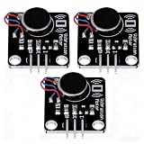
- High-Speed Vibration: 1027 phone motor delivers 9000RPM tactile feedback at 5V (60mA rated current) for clear alerts in smart devices
- PWM Intensity Control: MOS-driven design allows digital port/PWM adjustment of vibration strength (3.7-5.3V input range)
- Plug-and-Play Integration: 3mm mounting holes (15mm pitch) for secure installation, suitable for multiple project applications
- Compact & Efficient: 30×21mm module with 10mm×2.7mm flat motor fits wearables; 10MΩ insulation ensures safety
- Multi-Project Pack: Package includes 3pcs modules for interactive art, IoT notifications, or DIY haptic feedback systems
Prototype each technology without overbuilding
Fast resistive or FSR prototype
- Define the decision the sensor must make: contact/no contact, a few force bands, or a calibrated force estimate.
- Choose the sensing area and expected load. Add a compliant cover if the contact is localized, or a load-spreading layer if you need a broader response.
- Connect the element as a voltage divider or to a resistance-measurement input. Select the fixed resistor so the expected operating range uses a useful portion of the converter’s span.
- Sample at a rate comfortably above the fastest mechanical event, then apply only enough filtering to suppress noise without hiding contact timing.
- Record loading and unloading curves at several points. Store a per-sensor baseline and compensate for hysteresis rather than assuming one universal resistance-to-force equation.
- Cycle the assembly and inspect for permanent offset, cracking, delamination, and saturation before integrating it into the robot controller.
Capacitive array prototype
- Lay out one cell first. Keep the electrode geometry, dielectric thickness, and surrounding ground structure fixed while you establish a stable baseline.
- Measure the untouched capacitance and the change under known loads. Include the cable, connector, cover, and nearby structure in the measurement.
- Use a capacitance front end or converter designed for small changes. Provide shielding or a driven guard where parasitic coupling is comparable to the signal.
- For a matrix, characterize row-column crosstalk and allow settling time after switching each electrode. Check that the scan rate remains adequate when every pixel is active.
- Repeat measurements over temperature and humidity ranges relevant to the deployment. Store offset and gain corrections per pixel if manufacturing variation requires them.
- Protect the dielectric and electrodes from sweat, condensation, and mechanical abrasion; environmental changes can look like force.
Optical waveguide prototype
- Select the optical architecture based on the measurement: intensity for a simple threshold, FBG or wavelength tracking for strain, Fabry–Perot for cavity displacement, or speckle analysis for distributed deformation.
- Design the mechanical transducer before choosing the interrogator. The cover, diaphragm, foam, or elastomer must convert the target force into a repeatable optical change.
- Budget the optical path: source power, coupling loss, bend loss, detector range, and any splitter or multiplexer loss. Provide strain relief so handling the cable does not become the signal.
- Establish a reference measurement with no load, then apply known normal and shear loads separately. If the application includes both, collect a two-axis calibration rather than treating shear as noise.
- Secure connectors and protect the fiber from sharp bends, crushing, and contamination. Recheck the baseline after thermal cycling and after the package has been flexed repeatedly.
- Implement demodulation and fault checks. Flag loss of optical power, saturation, disconnected fibers, and implausible jumps instead of passing them to the robot controller as force.
How to compare published specifications fairly
Never rank devices using sensitivity alone. A sensitivity value is meaningful only with its force or pressure range, test method, loading rate, sample geometry, hysteresis definition, and conditioning circuit. A very high slope over 0–7 kPa may be unsuitable for a gripper that routinely sees hundreds of kilopascals.
A 2024 review of tactile systems reported example resistive sensitivities around 385 kPa−1 and capacitive examples from 1.78 × 10⁻³ to 0.815 kPa−1. The same review listed operating ranges from tens of kilopascals to more than 1,400 kPa. Those values demonstrate the spread of reported devices; they do not establish that one sensor class is inherently more sensitive.
When evaluating an optical paper, ask whether the quoted resolution refers to optical displacement, strain, pressure, or the final reconstructed force. Check whether the result comes from a single point, a distributed fiber, or an image-based array. For capacitive and resistive papers, identify whether the reported curve was corrected for temperature, drift, baseline subtraction, or machine-learning calibration.
The Tool Desk
Outbyte PC Repair FREEClear out junk files and repair common Windows errorsFree Scan →Outbyte Driver Updater FREEScan for outdated or missing drivers - takes under a minuteDriver Scan →| Test item | What to record | Why it changes the decision |
|---|---|---|
| Normal-force range | Minimum detectable load, usable span, and saturation point | Prevents a high-sensitivity low-range device from being used in overload conditions |
| Shear response | Output under tangential force with and without normal preload | Separates true shear measurement from cross-sensitivity |
| Hysteresis and creep | Loading/unloading difference and output after a sustained load | Shows whether force estimates remain trustworthy over a grasp |
| Drift | Baseline change over time, temperature, and humidity | Determines recalibration frequency |
| Dynamic behavior | Rise time, recovery time, sampling rate, and filtering | Confirms that the sensor can follow contact events |
| EMI susceptibility | Output with motors, drives, radios, and long cables active | Identifies whether optical isolation is worth its cost |
| Durability | Cycle count, overload behavior, abrasion, and package failures | Separates a laboratory demonstration from a deployable part |
Common failure modes and fixes
The resistive signal is noisy or unstable
Check the analog ground, cable routing, supply noise, and ADC reference before replacing the sensor. Add local decoupling, shorten or shield the cable, average only as much as the control loop permits, and mechanically constrain the sensing stack. If the baseline still moves under a constant load, characterize creep and use a time-dependent calibration or a different material.
The capacitive array reports force when nobody is touching it
Look for parasitic coupling from the enclosure, floating shields, moisture, and multiplexing transients. Establish a driven guard or grounded shield where appropriate, keep the excitation and measurement references consistent, and wait for the channel to settle after switching. Recalibrate after changing the cover, cable length, or mounting hardware.
The optical reading changes when the cable moves
The fiber may be acting as an unintended bend or strain sensor, or the connector may be losing coupling. Add strain relief, enforce the specified bend radius, isolate the sensing section from cable handling, and monitor total optical power separately from the tactile signal. A reference channel can help distinguish source or coupling drift from actual contact.
The sensor saturates during a grasp
Increase the mechanical load-spreading area, stiffen the protective layer, change the electrode or optical transducer geometry, or select a higher-range element. Increasing electronic gain does not restore information that the mechanical structure has already saturated.
Free tools Windows power users keep installed
One-click scans. No signup required.
Different pixels disagree under the same load
Inspect thickness, adhesive, preload, electrode alignment, fiber routing, and contact geometry. Map each pixel’s offset and gain, then test again after thermal and humidity conditioning. Per-pixel calibration is often necessary for arrays, but it should not hide a mechanically inconsistent assembly.
A practical decision framework
- Define the required output. If you only need contact detection, start with resistive hardware. If you need a calibrated force map or shear estimate, specify the range and error budget first.
- Measure the electrical environment. Run the candidate wiring while motors, drives, radios, and heaters operate. If interference consumes the signal margin, move optical sensing higher on the list.
- Set the packaging constraints. Thin flexible skins favor capacitive or optical layouts; inexpensive large pads favor resistive construction; electrically isolated tools favor optical designs.
- Choose the acceptable integration burden. Resistive electronics are simplest, capacitive electronics are moderate but calibration-heavy, and optical systems require the most specialized hardware and mechanical care.
- Prototype the mechanical stack. Test the cover, adhesive, preload, and load path with the cheapest suitable sensing element before committing to a production architecture.
- Run matched tests. Compare candidates at the same force range, loading rate, temperature, humidity, EMI condition, sampling rate, and lifetime target. Only then treat sensitivity or resolution numbers as decision evidence.
Bottom line by use case
| Your priority | Most defensible starting choice | Main compromise |
|---|---|---|
| Lowest cost and fastest proof of contact | Resistive sensor or FSR | Hysteresis, drift, and limited force metrology |
| Thin flexible multi-pixel skin | Capacitive array | Small signals, parasitics, shielding, and compensation |
| Operation beside strong motors or high-voltage equipment | Optical waveguide or fiber | Optical source, detector, coupling, and demodulation complexity |
| Electrical isolation or distributed high-resolution sensing | Optical waveguide or fiber | Specialized packaging and interrogation hardware |
| Exploratory robot-hand experiments | Resistive first, capacitive if a compact array is needed | May require redesign when accuracy or EMI requirements increase |
Optical, capacitive, and resistive tactile sensors are complementary tools. Select the class from the operating environment, force range, spatial requirement, and integration budget; then select the material and geometry that meet those requirements. The technology label is only the first decision.
Quick Recap
Product prices and availability are accurate as of the date/time indicated and are subject to change. Any price and availability information displayed on Amazon at the time of purchase will apply.

