
iTechGuides is reader-supported. When you buy through links on our site, we may earn an affiliate commission. As an Amazon Associate I earn from qualifying purchases. Learn more
For most visible archaeological footprints, use close-range photogrammetry first. A controlled series of overlapping photographs, scale bars and surveyed control points can produce a metrically defensible 3D record with richer color and texture than a scanner, usually at lower equipment cost. Add terrestrial or handheld LiDAR when lighting or surface texture is poor, when trench walls and recesses are occluded, or when rapid geometric capture is more important than photographic detail. For difficult excavations, registering both datasets is often the most complete approach.
The choice is not a contest between “accurate” and “inaccurate” technology. Accuracy depends on control, calibration, coverage, registration and independent checks. A phone can contribute useful evidence, but only a documented workflow with scale and quality checks makes a footprint model defensible.
What each method records
Close-range photogrammetry
Photogrammetry reconstructs three-dimensional geometry from overlapping photographs. Structure-from-Motion (SfM) software identifies common features in multiple images, estimates camera positions, creates a dense point cloud and builds a mesh. The same imagery can produce an orthophoto, elevation raster and textured model.
Free tools Windows power users keep installed
One-click scans. No signup required.
Its major advantage for footprints is information content: photographic color and fine sediment texture can help distinguish a true impression from a scrape, identify infill, and document tool marks around the track. It is also comparatively inexpensive because a capable interchangeable-lens camera or modern phone may be sufficient. The limitations are equally practical. The surface must contain trackable visual texture, shadows and glare must be controlled, and every part of the footprint must be seen from enough angles.
#1 Best Overall
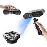
- 【Industrial-Grade Accuracy】Achieve single-frame accuracy up to 0.03 mm and volumetric accuracy of 0.03 mm + 0.05 mm x L(m), faithfully reproducing the finest surface details and complex geometries with exceptional consistency. Full-Field Structured Light accuracy reaches 0.08 mm; VCSEL mode delivers 0.10 mm @ 300-500 mm and 0.20 mm @ 500-800 mm. Engineered to meet the demanding requirements of 3D printing, reverse engineering, and precision modeling applications.
- 【Ultra-Fast Scanning & Robust Frame Rate】Multi-line Laser mode delivers up to 105 fps with NVIDIA GPU acceleration. Full-Field Structured Light mode achieves up to 5,000,000 points/s. The high frame rate ensures a smooth, uninterrupted scanning experience, especially suited for rapidly capturing large objects and complex scenes, significantly boosting overall workflow efficiency.
- 【AI-Powered & Photo-Grade Retopology】 AI object segmentation (Windows only) identifies your target in one click, tracks it throughout the scan, and auto-filters background noise — delivering clean data and streamlining post-processing. The patented 3D Gaussian Splatting converts point cloud and RGB data into true-to-life 1:1 photorealistic models; import photos from your phone or camera to apply real textures, then export in splat format for gaming, animation, and VR.
- 【All-Weather Outdoor Scanning】Multi-line Laser mode operates reliably up to 50,000 lux; with an outdoor filter attached, scanning remains stable in lighting conditions of up to 100,000 lux; VCSEL mode operates reliably in up to 100,000 lux ambient light. Designed to overcome lighting challenges, it provides consistent all-weather performance for construction sites, archaeological digs, and industrial fieldwork.
- 【5 Scanning Modes】NIR band supports Full-Field HD Scanning (markerless, fine structured light), Hybrid HD Scanning (dual projectors, fast high-quality modeling), and VCSEL Rapid Scanning (high-density pattern, fast markerless capture). Blue light band supports 30-Cross Laser Lines Scanning (handles high-reflectivity metals & dark objects) and Single-Line Deep Hole Scanning (captures from deep holes & narrow grooves). Five modes for comprehensive indoor and outdoor coverage.
Terrestrial, handheld and phone LiDAR
LiDAR measures distance by emitting laser pulses and recording their return. A terrestrial laser scanner can capture large, precise scenes rapidly; handheld and tablet sensors are more portable but generally cover less area and may have lower range or detail. Because the measurement is active, LiDAR is less dependent on visible texture and ambient illumination than photogrammetry.
LiDAR does not automatically supply the photographic evidence that makes archaeological interpretation easier. Some systems capture color by combining scans with photographs, but texture quality depends on the instrument and registration. Occlusion remains a geometric issue: a single scanner position cannot see behind a trench lip or into a recess, so multiple stations or a complementary camera dataset may still be necessary.
LiDAR and photogrammetry compared for footprints
| Decision factor | Close-range photogrammetry | LiDAR |
|---|---|---|
| Surface and lighting | Needs visible, repeatable texture and stable exposure; direct sun, reflections, deep shadows and moving light can reduce matching. | Less dependent on texture and illumination, although very dark, reflective or wet materials can affect some sensors. |
| Footprint texture | Records photographic color and micro-texture that support sediment and impression interpretation. | Primarily geometric; color quality varies by scanner and any separate camera used. |
| Occlusion and access | Requires a camera view; trench walls, undercuts and blocked edges can remain absent. | Multiple scan positions can capture geometry in difficult areas; inaccessible surfaces still require a different viewpoint or hybrid data. |
| Equipment cost | Generally lower, especially with an existing camera, calibrated scale and software. | Ranges from consumer tablet sensors to costly survey scanners; equipment cost is usually higher for high-precision systems. |
| Field capture speed | Many overlapping images take planning, but a footprint set can be photographed quickly. | Can capture geometry rapidly and may reduce image-alignment work, depending on scanner and scene. |
| Scale of work | Close-range capture suits individual prints, trackways and trench details; UAV photogrammetry suits site and landscape coverage. | Terrestrial systems suit controlled ground scenes; mobile or UAV LiDAR can extend coverage where permitted. |
| Metric defensibility | Requires camera calibration, scale or surveyed control, careful processing and checkpoints. | Requires scanner calibration, registration checks and a controlled coordinate frame; it is not control-free. |
Which method should you choose?
Choose close-range photogrammetry when the print is visible
Photogrammetry is the default for a cleanly exposed footprint or trackway with discernible sediment texture. It provides the interpretive color record and can deliver dense geometry at modest equipment cost. It is particularly effective when you can walk around the feature, maintain consistent lighting and place control points without disturbing the deposit.
Quick wins for a faster PC:
Clear out junk files and repair common Windows errorsFree Scan →Scan for outdated or missing drivers - takes under a minuteDriver Scan →Choose LiDAR when geometry or conditions dominate
Use terrestrial or other LiDAR when the surface is texture-poor, lighting cannot be controlled, or the excavation must be captured rapidly. LiDAR is also useful where camera views are constrained by trench walls or where you need reliable geometry from several scan stations. A scanner is not a substitute for scale and checkpoints; it is a different measurement instrument.
Use a hybrid for occluded or complex trenches
Capture the visible footprint and its color with photogrammetry, then add LiDAR for recesses, obstructed edges or textureless patches. Register the LiDAR to the controlled photogrammetric model rather than treating the two clouds as independent drawings. This approach follows the 2026 Tindari, Italy campaign, where UAV and terrestrial photogrammetry supplied the metric framework and iPad Pro LiDAR was added selectively to improve completeness in occluded or hard-to-access areas.
Rank #2

- What You Get: Raptor pro 3D Scanner, Scan Bridge Wireless Scanning, Calibration Board, Quick Start Guide
- Wireless scanning: compatible with wireless accessories, increasing convenience.
- Ultra-High Precision: Achieve 0.02mm accuracy in laboratory conditions, ideal for capturing intricate details.
- Blazing Fast Scanning: Scan at up to 60 frames per second (FPS) with a scanning rate of 660,000 points per second.
- Wide Scanning Range: Capture objects from 5mm to 2000mm in size, with a single capture range of 270mm x 170mm @300mm.
What published field campaigns show
These results are case studies, not universal performance guarantees. Their value is in showing how the methods behave under particular heritage-survey conditions.
| Study and setting | Methods and reported result | How to interpret it |
|---|---|---|
| Halos, Greece (Waagen and Lanjouw, 2026) | An Artec Leo structured-light scanner, a Nikon D5300 with Agisoft Metashape photogrammetry, and iPhone PolyCam low-cost LiDAR were compared on the same excavation profile for geometry, texture, expertise, ergonomics, processing time, precision and accuracy. | A direct, same-site comparison that illustrates trade-offs among high-end scanning, camera photogrammetry and phone LiDAR; it does not establish that one option wins every footprint project. |
| Cantillana, Spain (Applied Sciences, 2021) | In a semi-buried Roman mosaic excavation, SfM photogrammetry was reported as the most accurate and least limiting technique. The paper states that TLS was 40 times more expensive and that SfM produced 10 times more points. | Those ratios are case-study figures tied to that project’s equipment and processing, not universal prices or point-density guarantees. |
| Laetoli, Tanzania (Ruther, Smit and Kamamba, 2013) | Independent photogrammetric and laser-scan point clouds of an excavated hominid trackway agreed to approximately 0.3–0.4 mm external accuracy. | This demonstrates what a controlled heritage survey can achieve; it should not be quoted as the expected accuracy of an uncalibrated phone workflow. |
| Thessaloniki Toumba, Greece (ISPRS, 2021) | TLS, UAV photogrammetry, close-range photogrammetry and topographic surveying produced accurate digital surface models and photorealistic 3D outputs. Close-range imagery was more accurate than UAV imagery in that campaign. | Use close-range capture for individual footprints and trench details; use UAV methods for broader coverage when flight conditions and permissions allow. |
| Cahokia Mounds, Illinois (Vilbig, Sagan and Bodine, 2020) | UAV photogrammetry was described as a low-cost, comparable alternative to available LiDAR in areas with low-lying vegetation. | For open, low-vegetation terrain, time and available resources may matter more than a blanket technology preference. |
| Tindari, Italy (ISPRS, 2026) | UAV and terrestrial photogrammetry formed the metric framework; iPad Pro LiDAR was added selectively for occluded or hard-to-access areas. | Selective sensor fusion can improve completeness without replacing the primary controlled model. |
A defensible footprint-capture workflow
1. Establish the coordinate frame before taking pictures
Set a surveyed coordinate system appropriate to the excavation. Place scale bars or coded ground-control points around the footprint set, not only beside one print. Keep them rigid, visible and outside areas that might be sampled or excavated later. Record their coordinates, identification numbers and elevations. If a permanent datum is available, tie the local frame to it.
The Tool Desk
Outbyte PC Repair FREEClear out junk files and repair common Windows errorsFree Scan →Outbyte Driver Updater FREEScan for outdated or missing drivers - takes under a minuteDriver Scan →2. Plan coverage and lighting
Remove loose objects only when permitted by the excavation director, and document anything that remains. Photograph when illumination is stable. Avoid changing the sun angle, moving lamps or walking shadows during the sequence. For a single footprint, plan a ring of images from several heights plus oblique views that show the walls of the impression. For a trackway, overlap adjacent prints and include views that connect the entire sequence.
3. Capture sharp, overlapping images
- Set focus and exposure so the sediment is sharp and highlights are not clipped. Lock settings where the camera permits.
- Keep substantial overlap between consecutive frames; every important surface should appear in several images.
- Circle the feature at low, medium and higher viewpoints, then add oblique images aimed into the print’s depth.
- Keep the camera distance and angle changes smooth. Do not zoom between frames if it changes image geometry unpredictably.
- Photograph the scale bars and control points clearly, and take overview images that explain the footprint’s position in the trench.
- Record camera model, lens, focal length, image dimensions, capture time, lighting notes and any images rejected in the field.
A Nikon D5300 was used with Agisoft Metashape in the Halos comparison, but the named equipment is an example of a documented camera workflow, not a minimum requirement. A phone can work when it produces sharp, overlapping frames and the operator supplies the same control and metadata.
4. Process a calibrated model
- Copy the original files without altering them and preserve a read-only master set.
- Align images in the photogrammetry package, inspect camera positions and remove blurred or badly matched photographs.
- Enter measured control-point coordinates and scale bars, then optimize the camera solution.
- Build the dense point cloud and mesh at a resolution appropriate to the smallest footprint feature you intend to interpret.
- Export the textured mesh, orthophoto and elevation products in documented coordinate systems.
- Save the project file, software version, alignment settings, filtering choices, calibration data and processing date with the outputs.
Do not silently fill holes or smooth away irregularities. Mark interpolated regions and keep an unedited model so later researchers can distinguish measured geometry from visualization choices.
Rank #3

- AI Visual Tracking Technology: Equipped with a new generation of single-frame encoded structured light units that improve surface feature detection for smooth, marker free scanning
- High Precision Scanning: Achieves 0.05mm accuracy using blue light technology, making your model size closely approach reality for detailed reproduction
- Fine Resolution Capability: Features 0.10mm resolution with detailed point clouds that preserve object details providing refined models for printing or display projects
- Versatile Scan Range: Capable of scanning objects ranging from 15mm to 1500mm, accommodating a wide variety of object sizes
- Integrated Software Solution: JMStudio scanning software integrates scanning, editing, and optimizing into one seamless process for efficient workflow
5. Add LiDAR where the image model is incomplete
Scan recesses, trench walls or textureless zones from enough positions to avoid obvious shadowed gaps. Register the LiDAR cloud to the controlled photogrammetric frame using surveyed targets or clearly identifiable common features. Check whether the scanner’s coordinate units, vertical axis and georeferencing agree with the image model before merging.
Recommended Free Tools
6. Validate with independent checkpoints
Reserve some surveyed points as checkpoints rather than using every point to control the adjustment. Compare their measured and model coordinates, report residuals by axis and identify the largest error. Measure a few independent distances across the footprint or trackway with a survey instrument or calibrated scale. State where the model is interpolated, occluded or affected by poor texture. Preserve raw images, scans and control observations so another specialist can reproduce the result.
Can a phone produce a defensible 3D record?
Yes, but “phone” describes hardware, not quality. A phone camera can support a defensible photogrammetric record if the operator controls overlap, focus, lighting, scale, ground control and processing. A phone LiDAR sensor can efficiently supplement geometry, especially in a hybrid workflow, but its depth range and detail may be inadequate for small sediment features.
- Use the phone’s highest practical image quality. Disable modes that apply aggressive frame-to-frame processing or variable focus when they make images inconsistent.
- Keep the lens clean and the scene still. Moving people, blowing vegetation and changing shadows create mismatches.
- Include physical scale and surveyed control. A visually impressive model without known dimensions is not a metric record.
- Capture more views than seem necessary. Phone lenses are wide, and oblique close-ups help resolve impression walls.
- Document limitations. Report the phone model, capture application, software version, control method, expected ground sampling and any holes or smoothing.
The Halos comparison explicitly tested iPhone PolyCam low-cost LiDAR, while the Tindari campaign used iPad Pro LiDAR selectively. Those examples support using mobile sensors as part of a documented workflow; they do not prove that every phone can resolve a particular footprint’s toe ridges or sediment laminations.
Common failure modes and fixes
The model will not align
Blur, repetitive sediment texture, excessive overlap in one direction or changing exposure are common causes. Re-shoot missing viewpoints, add oblique images and remove frames with motion blur. If the scene is nearly textureless, use coded targets or supplement it with LiDAR.
PC Slower Than It Used to Be?
A free scan shows the junk files, broken settings and background clutter dragging Windows down - then fixes them in one click.Free scan · Windows 10 & 11Crashes, No Sound, or Screen Glitches?
Random freezes, missing sound and display glitches usually trace back to one bad driver. Find and replace yours safely.Free scan · under a minuteRank #4
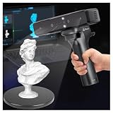
- Ultra-Precision & Versatility: Achieves 0.05mm accuracy with advanced infrared structured light technology, ideal for scanning objects from tiny screws (20mm³) to large automotive parts (2000mm³). Perfect for engineers, designers, and hobbyists seeking professional-grade 3D models.
- Wireless Freedom & Mobile Control: Built-in Wi-Fi and Lite Bridge battery handle eliminate cable restrictions. Use your smartphone as a real-time display via the Creality Scan app, enabling flexible scanning in any environment.
- Outdoor-Ready & Adaptive Lighting: Features DOE structured light and dual LED fill lights for crisp scans in low-light or bright outdoor conditions (up to 30,000 lux). Capture full-color textures with stunning realism, even in challenging settings.
- 30fps Real-Time Scanning & Anti-Shake: Smooth performance powered by a dedicated depth-computing chip and single-frame 3D imaging technology. Enjoy stable tracking at 30fps with minimal motion blur, ensuring fast and reliable results.
- User-Friendly Software & Cross-Platform Support: Compatible with Windows and macOS (recommended specs included). Seamlessly export models in OBJ/STL/PLY formats and utilize multi-angle stitching for complete 360° scans. Includes calibration tools and a portable case for on-the-go use.
The footprint is scaled incorrectly
A model can look correct while being dimensionally wrong if scale bars were not measured or control points were entered with incorrect units. Recheck bar lengths, coordinate units and point labels. Use independent checkpoints and report the residuals instead of applying an unexplained visual scale.
Edges are missing or warped
This usually indicates occlusion, insufficient oblique coverage or an alignment solution dominated by a flat surrounding surface. Add low-angle images aimed at the walls, capture the trench from additional positions and inspect camera residuals. Do not interpret a smoothed edge as measured evidence.
Lighting creates false relief
Raking shadows can exaggerate grooves, while glare can hide them. Compare the textured model with an untextured shaded-relief or elevation view. If possible, repeat capture under diffuse, stable illumination and retain both versions.
LiDAR and photographs do not register
Check that both datasets use the same coordinate frame and units, then identify a sufficient number of well-distributed common targets or surveyed points. Avoid registering only on one small corner. Examine residuals after transformation and document which dataset controls the final geometry.
How to report the record
A useful archive lets another researcher judge both the footprint and the measurement process. Include:
Best Value

- EASY TO USE FOR BEGINNERS – Perfect for entry-level users, DIY creators, and 3D printing enthusiasts. Quick start, with simple practice giving optimal scan results.
- SMOOTH WIRELESS SCANNING – WiFi6-powered Ferret Pro ensures fast, stable scanning. Works with Windows, macOS, Android, and iOS for flexible cross-platform use.
- HIGH-PRECISION 3D MODELS – Capture detailed 3D models with full-color 24-bit scanning and anti-shake technology. Offers up to 0.1mm accuracy with full-color scanning. Ideal for objects from 50mm to 2000mm. Not suitable for very small or highly detailed items like jewelry or precision parts.cccc
- VERSATILE OUTPUT & ENVIRONMENT – Export in OBJ, STL, or PLY. Works reliably in most settings, including outdoor light (<30,000 lux). Avoid reflective, transparent, or very dark surfaces for best results.
- LIGHTWEIGHT & PORTABLE – Weighing just 105g, carry and scan anywhere—home, studio, or on the go. Compact, convenient, and ready for travel.
- Site, trench, feature and capture date, with the excavation’s coordinate reference and datum.
- Camera, lens, sensor or scanner model, software and versions.
- Image count, image dimensions, capture geometry, lighting conditions and rejected frames.
- Control-point and checkpoint coordinates, scale-bar calibration and residual statistics.
- Point-cloud, mesh, orthophoto and elevation formats, resolutions and coordinate systems.
- Filtering, decimation, hole filling, smoothing, color balancing and any manual edits.
- Occluded, interpolated or texture-poor areas and the sensor used to fill them.
- Unmodified original images and scans, project files and a checksum or equivalent file-integrity record.
A practical decision checklist
- Is the footprint visible from several positions, with stable light and enough natural texture? Start with close-range photogrammetry.
- Do trench walls, recesses or obstructions block important edges? Plan extra camera positions, LiDAR, or both.
- Is rapid geometric capture more important than photographic color? Evaluate terrestrial LiDAR.
- Do you need site-scale or landscape coverage? Consider UAV photogrammetry, subject to permissions, weather and local rules.
- Can you establish surveyed control and independent checkpoints? If not, treat the output as a visual reference rather than a defensible metric record.
- Will the model support measurements of tiny ridges or tool marks? Match image resolution or scanner sampling to that smallest claim, and state the limit.
Frequently Asked Questions
Is LiDAR inherently more accurate than photogrammetry for a footprint trackway?
No. Accuracy depends on calibration, control, coverage, registration and validation. The Laetoli survey achieved approximately 0.3–0.4 mm external agreement between independent photogrammetric and laser-scan clouds, while the Thessaloniki Toumba campaign found close-range imagery more accurate than UAV imagery. Those are controlled case results, not universal rankings.
Should I use UAV photogrammetry for individual footprints?
Usually not as the sole capture method. UAV imagery is valuable for site and landscape coverage, but close-range imagery is generally better for individual prints and trench details. The Toumba study reported better accuracy from close-range than UAV imagery in its campaign.
How many control points do I need?
The required number and spacing depend on the footprint area, coordinate system and survey method. Place several well-distributed points around the set, reserve independent checkpoints, and report residuals. A single scale bar beside one print cannot reveal deformation elsewhere in the model.
What’s actually slowing this PC down?
Pick the symptom - the matching free tool is one click away.
Can I combine a photogrammetric mesh and a LiDAR scan after capture?
Yes. Register the LiDAR to the controlled photogrammetric coordinate frame using surveyed targets or common features, check residuals across the scene, and document which areas came from each sensor. Keep both original datasets and the unmerged versions.
The Bottom Line
For visible archaeological footprints, make controlled close-range photogrammetry your baseline. Add LiDAR when texture, lighting or access limits the camera record, and validate either method with surveyed control and independent checkpoints. The strongest documentation is the one whose measurements, limitations and raw evidence another researcher can audit.
Quick Recap
Product prices and availability are accurate as of the date/time indicated and are subject to change. Any price and availability information displayed on Amazon at the time of purchase will apply.

