
Quick wins for a faster PC:
Scan for outdated or missing drivers - takes under a minuteDriver Scan →Repair Windows errors before they cause bigger problemsFix Now →iTechGuides is reader-supported. When you buy through links on our site, we may earn an affiliate commission. As an Amazon Associate I earn from qualifying purchases. Learn more
The clearest spin-ice visualization combines three synchronized views: a temperature–field (and, when needed, pressure, anisotropy, or disorder) phase map; a real-space map of arrows, vertices, and monopole-like charges; and a reciprocal-space structure-factor map. The phase map tells you where behavior changes, the real-space panel shows which defects cause it, and pinch points in the structure factor reveal the collective Coulomb-phase correlations behind the ice manifold.
What you are actually plotting
Spin ice is a frustrated magnetic system in which spins sit on corner-sharing tetrahedra in bulk pyrochlores or on lithographically patterned nanomagnets in artificial spin ice. Each spin has a local easy axis, so it can be represented as pointing “in” toward a vertex or “out” from it. The local organizing constraint is the two-in/two-out ice rule: two spins point into a tetrahedron (or vertex) and two point out. This arrangement minimizes the effective magnetic charge at the vertex while leaving many configurations nearly degenerate.
A phase diagram is not just a colored picture of simulation output. It is a map from control parameters to measured observables, with a stated criterion for every boundary. A useful figure therefore connects the same parameter point across three coordinate systems:
What’s actually slowing this PC down?
Pick the symptom - the matching free tool is one click away.
- Parameter space: temperature and magnetic field are the usual axes; pressure, anisotropy, lattice geometry, or disorder can be added when they are part of the model.
- Real space: arrows on individual spins, vertex classes, and strings of flipped spins expose local order and defects.
- Reciprocal space: the spin or magnetic-charge structure factor shows long-range correlations, including pinch-point singularities associated with a Coulomb phase.
Keep these views tied to the same field, temperature, lattice, and simulation snapshot. Otherwise it is easy to attribute a reciprocal-space feature to a real-space pattern that was never present in the plotted configuration.
#1 Best Overall
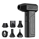
- Powerful Turbo Fan:CAGIWIRU Electric Air Duster have reached speed up to 130000RPM,Can efficient remove dust and debris.With LED light and Three Adjustable Speed to meet with different cleaning tasks.
- With Attached USB C Fasting Charging cable.Charing 3 hours,Enjoy up to 240 minutes of use on the lowest setting, For third speed can use for 25mins.with four charging options to meet with your needs.
- Wide Application: attached 5 different nozzles,making it suitable for a variety of scenes, such as car,pet, pc, keyboards, and other electronic devices. It also serves for office and home clean duster.
- Handy Design & Portable:Cordless air duster electric nozzle is Light weight and small size, design and comfortable to hold and space saving, convenient to carry around. You can put it in your room or inside the car without taking up space.
- Economical &Reusable: Built durable materials with a long-lasting battery,our CAGIWIRU air duster it's a sustainable alternative to disposable air cans.
How to build a spin-ice phase diagram
1. Choose the control-parameter grid
Start with a rectangular temperature–field grid if you are establishing baseline behavior. Label the field direction explicitly—for example, a field along cubic [111] is not interchangeable with a field along another crystallographic direction. Add a third parameter only when it answers a physical question, such as how pressure, exchange anisotropy, geometric disorder, or a designed lattice defect changes a boundary.
Use a coarse grid to locate crossovers and suspected transitions, then refine the grid around sharp changes. The plotted range should include a high-temperature region where ice correlations are weak and a low-temperature or low-field region where the constrained manifold is developed. If the study concerns driven dynamics rather than equilibrium, record the sweep rate or drive protocol; a field sweep and an equilibrated field scan are different measurements.
2. Measure observables at every grid point
For each temperature–field pair, equilibrate the model and calculate observables from many post-equilibration configurations. The following set covers the questions most readers have when interpreting a map.
| Observable | What it reveals | How to display it |
|---|---|---|
| Magnetization | Response to the applied field and field-selected order | Color map or contours; state the component and normalization |
| Susceptibility | Enhanced fluctuations and possible transition regions | Color map with peak contours; specify whether obtained from fluctuations or a derivative |
| Heat capacity | Thermal redistribution of energy and latent-heat-like features | Color map or line cuts at selected fields |
| Energy | Changes in the dominant interaction regime | Line cuts and derivative-based boundary checks |
| Ice-rule or defect density | Fraction of vertices that violate two-in/two-out | Color map; distinguish the two charge signs |
| Order parameter | Broken symmetry or field-selected ordering | Color map with a declared definition and symmetry sector |
| Correlation length or structure factor | Growth and anisotropy of collective correlations | Selected reciprocal-space panels and peak or pinch-point metrics |
No single observable defines every phase boundary. Mark a boundary where an observable changes sharply, where a susceptibility or heat-capacity peak develops, or where hysteresis and finite-size scaling support a transition. A smooth color gradient by itself is evidence of a crossover, not proof of a thermodynamic phase transition.
3. Treat finite size and uncertainty as part of the diagram
Run multiple independent random seeds at each parameter point. Report means and uncertainty bands when replicas permit them. A single Monte Carlo history can make noise look like a narrow phase boundary, and it cannot establish experimental precision. Repeat key points on more than one system size when you claim a transition; a peak that shifts or broadens strongly with size may be a finite-size effect.
For a driven or disordered artificial-ice calculation, retain the preparation history, field protocol, and switching rates. Hysteresis may be the central result rather than a sampling failure. Plot up-sweep and down-sweep data separately instead of averaging them away.
Rank #2

- Screen Cleaner is Your Screen’s New Bestfriend! - EVEO is proud to present a screen cleaner that’s perfectly suited for your TV. Meet your new screen cleaner, computer screen cleaner, laptop cleaner, iPad cleaner, Macbook,tv cleaner or any other electronic device. Our screen cleaner spray and wipe along with the included plush microfiber cloth, easily removes dust, fingerprints & other smudges on the screen’s surface. Clean effectively for a streak-free screen
- Gentle on your Screens - Our screen cleaner spray and wipes is compatible to be used even for the most sensitive LCD, LED, CRT, and OLED screens in proper use. Be at ease knowing that this product is compatible with all the major brands: LG, SONY, Samsung, Sharp, iPad, iPhone, Android screens, Kindle, PC monitors - we’ve got you covered! Can be used as LCD screen cleaner, tv cleaner, smart tv screen cleaner, and more
- Premium Super Soft Plush Microfiber Cloth - Included in this efficient screen cleaning kit. This screen cleaner spray and wipe has our signature plush microfiber cloth specially designed to comply with screens and monitors and leave them streak-free. Has been shown to effectively absorbs stubborn stains, zero streaks, and no fiber shedding. Always use this together with our screen cleaner for the best results
- Easy-to-Use Screen Cleaner Kit + microfiber cleaning cloth - The EVEO Screen Cleaning Kit will easily be your new favorite tool when it comes to taking care of the things you love most, quick and easy solution for a streak-free screen. Simply screw on the sprayer gun on the screen cleaner bottle. Spray the cleaning liquid onto the microfiber cloth, then wipe the screen until desired cleanliness & shine is achieved.
- Quality Screen Care Kit Worth Purchasing - Enjoy a convenient Screen Cleaner anytime, anywhere you need it. Your satisfaction is our top priority. We stand behind the quality of our products and that’s why, you shouldn’t be worrying at all. We manufacture the Best Screen Cleaner. and can be used for laptop cleaning kit, laptop screen cleaner, tv screen cleaner for smart tv. MacBook screen cleaner, monitor cleaner or screen cleaner spray for electronic devices with microfiber cleaning cloth
Real-space maps of vertices and monopole-like defects
Draw the local geometry before the data
Place a small tetrahedron or artificial-ice vertex schematic beside the first data figure. Draw every spin as an oriented arrow and make the local easy axis visible. This lets readers distinguish “in” and “out” from an arbitrary screen direction. For a bulk pyrochlore, group the four spins belonging to each tetrahedron. For an artificial array, group nanomagnets meeting at the same designed vertex.
The Tool Desk
Outbyte Driver Updater FREEFix the driver behind crashes, sound loss and screen glitchesFind Drivers →Outbyte PC Repair FREEClear out junk files and repair common Windows errorsFree Scan →Use a consistent arrow convention in every panel. If the physical spins are elongated nanomagnets, draw the arrow along the long axis and state which end is treated as the magnetic north pole. Do not infer a vertex charge from color alone; the arrow directions must remain readable at the final publication size.
Classify vertices and charge signs
| Vertex configuration | Ice-rule status | Suggested rendering | Interpretation |
|---|---|---|---|
| Two-in/two-out | Satisfies the ice rule | Neutral or unfilled marker | Locally charge-minimizing state in the ice manifold |
| Three-in/one-out | Violation | One charge color, such as red | Positive emergent charge under the chosen convention |
| One-in/three-out | Violation | Opposite charge color, such as blue | Negative emergent charge under the chosen convention |
The labels “positive” and “negative” are convention-dependent. State your convention in the caption and use it consistently. The physically important information is that the two three-in/one-out variants carry opposite emergent charges.
Show strings without implying a new particle
When opposite charges are connected by a chain of flipped spins, draw that chain as a thin line or highlighted sequence. Such strings make the history of a defect pair visible in a snapshot. They are not an additional vertex type, and a line should not be drawn through every correlated region simply because the arrows are aligned. Define the rule used to identify a string—for example, a contiguous set of spins changed relative to a reference configuration or a path selected by the simulation’s defect-tracking algorithm.
Plot a vertex-charge histogram alongside the map. It quantifies whether defects are rare isolated pairs or a dense population. A density map and a snapshot answer different questions: the map shows location and connectivity, while the histogram shows the ensemble frequency.
Do these 3 things before closing this tab:
1Fix the driver behind crashes, sound loss and screen glitches2Repair Windows errors before they cause bigger problems3Scan for outdated or missing drivers - takes under a minuteKeep lattice defects separate from magnetic defects
Artificial spin ice can be deliberately fabricated with edge dislocations or other topological changes in the lattice. Those are geometric defects in the array itself. A three-in/one-out or one-in/three-out vertex is a magnetic defect in the spin texture. Use different symbols, colors, or panels for the two. Otherwise a reader may mistake a structural dislocation for an emergent monopole.
Rank #3

- 【Large size】:Measuring 800 x 300 mm/ 31. 5×12 inches, which is wider and taller than others. Large mouse pad can perfectly fit your keyboard and mouse of any size, and there is also ample space for peripherals such as phones, tablets, etc.
- 【LED backlight mouse pad】:Blade Hawks RGB mouse pad provides 7 static modes and 7 dynamic modes will give you the options you are looking for. Power-off memory function remembers the last lighting mode you selected. The super glow fiber Chroma will give you a colorful gaming setup that you want.
- 【Anti-slip rubber base】:Made from Natural rubber, this gaming mousepad will firmly grip your desktop, allowing you to enjoy the ultimate precision in the games you are most passionate about. It also comes with a texture that enhances this ability even further.
- 【Smooth and waterproof surface】: Micro-textured cloth surface, for extremely precise mouse control and a smooth movement. When liquid splashes on the gaming mouse pad, it forms water droplets and slides down. Will not delay your work or gameplay.
- 【Plug and play】: This mouse and keyboard pad is powered by USB, plug and play, no driver required. One button control light modes. Press one time to change the lighting mode, press twice to change the brightness, press and hold about 3 seconds turn ON/OFF.
Experiments on kagome artificial spin ice established direct magnetic-force-microscopy imaging of local configurations, making this real-space language experimentally grounded. In bulk pyrochlores, individual spins are not normally imaged in the same way; neutron scattering and thermodynamic measurements provide the complementary evidence.
Reciprocal-space maps and the meaning of pinch points
Calculate a structure factor, not just a Fourier transform of a picture
For each retained configuration, project the spin vectors onto the reciprocal-space grid and calculate the spin structure factor or magnetic-charge structure factor. Average intensities over independent configurations only after the equilibration cut. State whether the plotted quantity is a component-resolved spin structure factor, a polarization-resolved magnetic-scattering intensity, or a charge structure factor; these choices can emphasize different features.
Display reciprocal-space intensity with a perceptually ordered color scale and fixed limits when comparing parameter points. Mark reciprocal-lattice directions and units, and use identical orientation conventions in every panel. A bright spot caused by a changing color range is not a physical enhancement.
Free tools Windows power users keep installed
One-click scans. No signup required.
Read pinch points as a collective-correlation signature
Pinch points are sharp, anisotropic singular-looking features in the structure factor. In spin ice they diagnose the constrained, divergence-free correlations of a Coulomb phase rather than a conventional Bragg-ordered state. Their shape and intensity change as defects, temperature, field, or disorder modify the ice manifold.
A pinch point is not, by itself, a map of monopole locations. Use the real-space charge panel to locate three-in/one-out and one-in/three-out vertices, then use the reciprocal-space panel to show the collective correlations generated by the surrounding spins. The two panels should be computed from the same parameter point and, when possible, the same ensemble of snapshots.
Make the comparison reproducible
- Keep the reciprocal-space window and pixel resolution fixed across the parameter sweep.
- State the reciprocal-space center, crystallographic orientation, and any polarization or form-factor weighting.
- Show at least one ice-manifold point and one defect-rich point so readers can see how the anisotropic feature evolves.
- Do not call a broad maximum a pinch point without demonstrating its characteristic anisotropy and its connection to the ice-rule correlations.
The cluster-algorithm work on nearest-neighbor spin ice demonstrated high-resolution color maps of these features. Its methodological lesson is practical: an update scheme that explores the ice-rule manifold efficiently can produce a cleaner estimate of reciprocal-space correlations than a local sampler that remains trapped.
Rank #4

- 【Softer and More Comfortable】Vaydeer wrist rest has unique diamond pattern, which is the combination of softness and aesthetics. The materials of wrist rest are improved into higher quality memory foam and covered with silky smooth lycra. The computer wrist rest makes you as comfortable and cushiony as like rest your wrists on clouds.
- 【Ergonomic Wrist Saver】The wrist rests for keyboard and mouse comes with a 17.32×3.15×0.83 inch keyboard wrist pad and a 5.94×3.15×0.83 inch mouse wrist support. Based on ergonomic design, the unique concave shape is the perfect fit for your wrist joints. The wrist rest pad fits most computer keyboards and laptops, improve hand and wrist posture, release your wrist and arm stress.
- 【Non-Slip Rubber Bottom】Featuring an anti-skid silicone base on the bottom, this wrist keyboard support stays firmly in place on your desk, preventing the padding from sliding around, ensuring stable and consistent wrist support during extended computer sessions.
- 【Better Experience & Pain Relief】Our keyboard arm rest is beneficial to alleviate the soreness caused by direct contact and friction between your arm and a hard desk surface, reducing the risk of wrist fatigue or carpal tunnel. The soft texture of memory foam can evenly distribute the pressure around your wrists and provide good support with just enough give.
- 【Helpful in Multiple Scenarios】Whether you're working, studying, writing, typing, gaming, this keyboard and mouse rest combo is an essential accessory to add comfort and support to your hands and wrists. It’s also a great gift for men, women, family, friend, coworker, gamer, teacher, etc.
Field–temperature examples worth drawing
[111] field: kagome ice and the high-field transition
For a dc field along cubic [111], one spin on each tetrahedron is selected by the field while the remaining spins form kagome sheets. At modest field, the selected spin and the residual two-in/two-out constraint produce a kagome-ice regime. In a phase diagram, mark this region by the persistence of ice-rule correlations, the field-selected magnetization, and the corresponding reciprocal-space features.
At larger field, the ice rule is driven toward a three-in/one-out configuration. The field–temperature map can therefore show a first-order transition line separating the kagome-ice regime from the high-field state; that line terminates at a critical endpoint. Use hysteresis, susceptibility or heat-capacity anomalies, and finite-size checks together rather than drawing the line from magnetization alone. The [111]-field dynamics literature provides the physical example, but your own simulation must still state its interaction model and sweep or equilibration protocol.
Ferromagnetic Ising pyrochlores
In a ferromagnetic Ising pyrochlore, two-in/two-out configurations are highly degenerate and support the classical spin-ice phenomenology. Ho2Ti2O7 and Dy2Ti2O7 are canonical examples associated with emergent monopoles. A 2024 Physical Review B study combined field–temperature mapping, bulk characterization, and neutron scattering for a ferromagnetic-Ising-pyrochlore system. When adapting that example, distinguish what comes from bulk thermodynamics from what comes from reciprocal-space scattering; they constrain the phase assignment in different ways.
Classical, quantum, and driven cases
Do not merge classical thermal defects, quantum excitations, and driven switching into one visual category. A classical Monte Carlo phase map samples thermal configurations. A quantum model may require a classification of quantum monopole-like excitations and a different observable set. A kinetic Monte Carlo study of artificial spin ice emphasizes real-time switching, barriers, and disorder. Label the model class and measurement protocol in the figure title so a reader does not compare unlike quantities as if they were the same phase diagram.
A simulation workflow that produces defensible figures
- Define the lattice and degrees of freedom. Specify bulk pyrochlore tetrahedra or the artificial-ice vertex geometry, the local easy axes, interaction range, field direction, and whether spins are classical Ising variables or a richer model.
- Select an ensemble sampler. Use single-spin Metropolis updates as a baseline. Use loop or cluster updates when the ice-rule manifold causes local updates to become inefficient. Use kinetic Monte Carlo when switching times, disorder, or real-time trajectories are central.
- Initialize independently. Use several seeds and, where useful, contrasting starts such as a random state and an ice-rule-respecting state. Keep the initialization metadata with the run.
- Equilibrate at every temperature and field. Discard an explicitly defined equilibration segment before collecting measurements. Near a first-order line or a critical endpoint, extend equilibration and check for hysteresis or multimodal energy and magnetization distributions.
- Collect configurations at separated intervals. Store snapshots far enough apart to reduce autocorrelation. The snapshots are needed for vertex maps, charge histograms, correlations, and structure factors—not merely for making an attractive picture.
- Compute local observables. For each tetrahedron or vertex, count in and out spins, assign the charge class, and calculate defect density and charge–charge correlations. Keep positive and negative charges separate before combining them into a total density.
- Compute global observables. Record energy, magnetization, susceptibility, heat capacity, and the order parameter used for phase labeling. Preserve per-replica values so uncertainties can be estimated.
- Compute reciprocal-space quantities. Transform the same snapshots to obtain the spin or charge structure factor. Use a consistent reciprocal-space grid and normalization throughout the parameter sweep.
- Locate candidate boundaries. Identify peaks, discontinuities, hysteresis, or rapidly changing defect and correlation measures. Refine the grid around candidates and test more than one system size before calling a line a transition.
- Assemble synchronized panels. Select one or more parameter points and show the phase-map marker, the real-space configuration, the charge/vertex legend, and the reciprocal-space map together. Include uncertainty bands or replicate scatter where the data support them.
A compact implementation outline is:
for field in fields:
    for temperature in temperatures:
        states = equilibrate_and_sample(model, temperature, field, sampler, seeds)
        vertices = classify_vertices(states, lattice)
        observables = measure_bulk_properties(states)
        structure = measure_structure_factor(states)
        save(temperature, field, vertices, observables, structure)
The function names are descriptive rather than a software requirement. The important reproducibility details are the sampler, equilibration rule, seed count, snapshot spacing, normalization, and transition criterion.
Bulk pyrochlore versus artificial spin ice
| Comparison axis | Bulk pyrochlore | Artificial spin ice |
|---|---|---|
| Geometry | Corner-sharing tetrahedra in a crystalline material | Patterned nanomagnets arranged on designed periodic or aperiodic lattices |
| Control over lattice | Set by crystal structure; pressure or anisotropy may tune behavior | Geometry, nanomagnet shape, disorder, and edge dislocations can be designed |
| Typical direct evidence | Thermodynamic measurements and neutron scattering | Real-space imaging, including magnetic-force microscopy, plus ensemble analysis |
| Defect visualization | Usually inferred from scattering, thermodynamics, and simulations | Individual vertices and charge signs can be rendered directly from images |
| Dynamics | Often treated as equilibrium or field-dependent bulk behavior | Driven switching and kinetic Monte Carlo can be central |
| Disorder/topological control | Constrained by the material and sample | Fabrication can introduce controlled disorder or lattice defects |
| Reciprocal-space signature | Neutron-scattering-compatible structure factors and pinch points | Structure factors calculated from images or simulations; reciprocal-space maps remain useful |
These are complementary platforms, not interchangeable substitutes. Artificial arrays make local vertices and designed defects unusually accessible, while bulk systems connect the same ice-rule physics to crystalline materials and bulk probes.
Best Value

- 【No Drill Mounted】Cable management tray can be assembled in as little as 3 minutes or less-simply. Side clips easily clampe the edge of desk, pass through the holes on the sides, and secure excess cables with baskets. Desk cable management supports inward or outward installation to meet your needs in different scenarios, and provides you with great convenience when collecting and organizing wires.
- 【Rubber Pad Protects Desk】Wire organizer under desk built-in soft rubber pads on the clamp protect your desk from scratches, so you will not damage your furniture or office.
- 【Sturdy and Beautiful】Cord management under desk is made of high-quality carbon steel and holds about 15 lbs. The wire basket has 2 holes on each side of the tray to enable your cables to pass freely. Cable baskets are suitable for desk thickness use from 0.4" to 2.4".
- 【Space Saving & Keep Organized】Desk cable management tray holds all your power cords, outlet strips, USB hubs and computer transformers hidden from your feet, and the data cables will not enter the vacuum cleaner to keep your desk clean and tidy. Desk wire organizer is also suitable for use in the kitchen and outdoors.
- 【Reduce Safety Risks】Cable tray under desk keeps all plugs away from your kids, no more worry about tripping. Using 2 holes wire tray saves extra space, helps you easily cabling and wire protection. The mesh design is not easy to accumulate dust, but avoids safety accidents caused by messy wires.
Common visualization mistakes and fixes
Calling every sharp color change a phase transition
Symptom: a narrow band appears in a heat map, but no peak, hysteresis, size dependence, or independent observable supports it.
Fix: label it a crossover until a declared transition criterion and finite-size check agree.
Mixing parameter points between panels
Symptom: the real-space snapshot is taken at one temperature while the structure factor comes from another.
Fix: store parameter metadata with every snapshot and generate synchronized panels from the same record.
Confusing a lattice dislocation with a monopole
Symptom: a missing or shifted vertex is colored like a three-in/one-out charge.
Fix: use separate overlays and legends for geometric defects and spin-texture charges.
Recommended Free Tools
Hiding uncertainty behind a smooth map
Symptom: one simulation seed produces a polished boundary with no error estimate.
Fix: show replicate spread, state the number of seeds, and mark regions where sampling is slow or hysteretic.
Using a misleading color scale
Symptom: independent panels use different limits, or a rainbow map creates artificial bands.
Fix: use a perceptually ordered scale, fixed limits for comparisons, labeled units, and contour lines only for stated criteria.
Drawing arrows without defining “in” and “out”
Symptom: readers cannot reproduce the charge labels from the image.
Fix: add a tetrahedron or vertex schematic before the first data panel and state the sign convention in the caption.
Over-interpreting a pinch point
Symptom: any bright reciprocal-space maximum is called a Coulomb-phase signature.
Fix: demonstrate anisotropy, keep the reciprocal-space scale consistent, and connect the feature to ice-rule correlations and the corresponding real-space ensemble.
Figure and caption checklist
- Axes include units, temperature and field ranges, and the field direction.
- The model identifies bulk tetrahedra or the artificial-ice lattice and states whether it is classical, quantum, equilibrium, or driven.
- A schematic defines the in/out convention and the sign of each charge.
- Phase boundaries cite the observable or criterion that places them.
- Real-space maps distinguish ice-rule vertices, positive and negative charges, strings, and geometric lattice defects.
- Reciprocal-space panels state the structure-factor definition, orientation, normalization, and color limits.
- Replicate count, uncertainty treatment, equilibration, and sampler are documented.
- Snapshots and structure factors correspond to the same parameter point.
The result should let a reader move from a colored phase map to a specific configuration, count its defects, and then verify how those local objects alter collective correlations. That chain—from control parameters to vertices to reciprocal-space structure—is the most reliable way to visualize magnetic phases and topological defects in spin-ice models.
Quick Recap
Product prices and availability are accurate as of the date/time indicated and are subject to change. Any price and availability information displayed on Amazon at the time of purchase will apply.

