
iTechGuides is reader-supported. When you buy through links on our site, we may earn an affiliate commission. As an Amazon Associate I earn from qualifying purchases. Learn more
For most air-cooled IT equipment in ASHRAE classes A1 through A4, set the normal equipment-inlet dry-bulb target within 18–27°C. For qualifying high-density, air-cooled H1 equipment, the recommended range is tighter at 18–22°C. Humidity is not a single relative-humidity set point: manage dew point and RH together, prevent condensation, and use the 70% RH ceiling only when corrosion-coupon results support it. These are equipment-inlet conditions, not a blanket thermostat setting for every room. Verify the environmental class and OEM limits of every installed device before changing controls.
Quick reference: recommended and allowable ranges
ASHRAE’s 2021 Thermal Guidelines, reproduced in the 2023 ASHRAE Handbook chapter, separate a normal recommended operating envelope from a wider allowable envelope. Recommended conditions are the routine objective for reliability and service life. Allowable conditions are boundaries at which manufacturers test equipment for functionality; they can support controlled excursions, such as free-cooling operation or a maintenance event, but they are not the default target.
| Equipment class | Recommended dry-bulb temperature at equipment inlet | Allowable dry-bulb range | Humidity guidance |
|---|---|---|---|
| A1 | 18–27°C | 15–32°C | −9°C to 15°C dew point, with an RH ceiling of either 70% or 50% depending on corrosion-coupon results; conditions must remain noncondensing. |
| A2 | 18–27°C | 10–35°C | |
| A3 | 18–27°C | 5–40°C | |
| A4 | 18–27°C | 5–45°C | |
| H1 high-density, air-cooled | 18–22°C | 15–25°C |
The figures are published ASHRAE guideline values, not a guarantee that every server, storage array, network appliance or accelerator accepts them. A device’s nameplate, installation guide and warranty terms take precedence when they are more restrictive. Mixed-class rooms must be controlled for the most restrictive equipment or zoned so each class receives an appropriate inlet environment.
What temperature should a data center be?
Use the inlet temperature of the IT equipment as the control reference. The air reaching a server’s front intake can differ materially from a wall thermostat, return-air sensor or an average room reading. Hot and cold aisles, rack loading, perforated-tile placement, fan speed, containment leakage and cable openings all create local differences.
#1 Best Overall

- Ventilation Fan: Designed to quietly ASUS GT/RT- AC5300 , cool Xboxs, CPU/ GPU, Playtations, Rokus, TVs, receivers, mondems, routers, DVRs, window fans ,network appliances, DIY aquarium cooling and other audio video electronics
- Variable Speed Control: 110V - 220V Fan power supply with speed control function, turn the knob to adjust the speed, 4V - 12V adjustable fan speed,and can turn off the fan . | Input: 100V - 240V 50/60Hz | Output: DC 3-12V 200-2000ma
- DIY Vertical Window Fan: Can both vertical and horizontal, provide efficient cooling and ventilation. Mining rigs rely on the cooling power of fans for optimal operation.Double Metal Protective, the fan is equipped with double metal protective net
- Easy to Install: Draw out air in refrigerators, provide ventilation in greenhouses, prevent amplifier overheating, and vent hot air from living room consoles like PS4. Y cable connects 2 fans, two fans can be 42cm/16.5 in far away from each other
- Dual Ball Bearing: 240mm x 240mm x 25mm / 9.45in(L) x 4.72in(W) x 1in(H) in in total. | Rated Voltage :12V | Rated Current: 0.93A at full speed | Airflow: (82CFM)x4 at 12V | Speed: 2500 RPMx4
An 18–27°C recommendation therefore means that representative server inlets should remain in that interval during normal operation. It does not mean every point in the room must read the same value, nor that a single sensor in the return-air path proves that all racks are within range. In a contained cold aisle, for example, the cold-aisle supply and rack-inlet readings are more useful for control than a sensor mounted above the ceiling.
Why inlet conditions matter
- Server fans and internal components respond to the temperature of incoming air, not the room’s nominal thermostat setting.
- High-density racks can draw down aisle temperature locally while exhausting enough heat to create hot spots at adjacent inlets.
- Air mixing, bypass air and recirculation can make two racks on the same row experience different temperatures.
- Reliability decisions should use the warmest representative inlet and the distribution of readings, not only a room average.
Recommended versus allowable: how to use the two envelopes
Recommended conditions
The recommended envelope is the normal operating objective. Staying inside it gives the broadest margin for aging fans, clogged filters, uneven airflow, sensor error and short control disturbances. It is the prudent baseline for capacity planning, alarm thresholds and operating procedures.
Allowable conditions
The allowable envelope is where datacom equipment manufacturers test equipment to verify that it will function within those environmental boundaries. Allowable values can make more hours of economizer or free-cooling operation possible, and they may be useful during a controlled service event. They should be treated as excursion limits with a documented reason, duration and recovery plan.
What’s actually slowing this PC down?
Pick the symptom - the matching free tool is one click away.
Prolonged exposure outside the recommended range, particularly near the extremes of the allowable environment, can reduce equipment reliability and longevity. Operating outside the allowable range carries a risk of malfunction or catastrophic failure. A control system that can technically hold 35°C is not evidence that 35°C is an appropriate everyday set point for an A1 room.
Identify the installed equipment class before changing set points
A1 through A4 and H1 are environmental classes, not performance tiers that a facility can select arbitrarily. The class depends on the equipment’s design and the manufacturer’s qualification. Inventory every rack and record the class stated in its documentation. Do not infer class from a server’s age, processor type or rack power alone.
| Class | What the published range tells you | Control implication |
|---|---|---|
| A1 | Most restrictive of the listed A-class allowable temperature ranges: 15–32°C. | Use the A1 limits when A1 devices share a zone with less restrictive equipment. |
| A2 | Allowable temperature is 10–35°C. | Do not assume the wider boundary changes the recommended 18–27°C objective. |
| A3 | Allowable temperature is 5–40°C. | Confirm the OEM’s environmental statement and any humidity or altitude conditions. |
| A4 | Allowable temperature is 5–45°C. | Use the wider boundary only with a managed strategy and suitable equipment qualification. |
| H1 | High-density air-cooled equipment has a recommended 18–22°C range and a 15–25°C allowable range. | Keep H1 zones tighter; do not apply A3 or A4 limits simply because the rack is air-cooled. |
When a vendor specifies a narrower operating range, the vendor requirement controls. When documentation is missing, pause a set-point change and obtain the relevant environmental specification rather than treating the broadest ASHRAE class as permission.
Rank #2
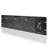
- An intelligent fan system designed for cooling audio video, DJ, server, network, and IT equipment racks.
- Protects rack-mount equipment from overheating, performance issues, and shortened lifespans.
- Programmable thermostat controller with automated speed control, alarm warnings, and backup memory.
- Premium anodized aluminum construction with CNC-machined detailing for a professional appearance.
- Size: 3U Rack Space | Design: Intake | Airflow: 60 to 300 CFM | Noise: 12 to 38 dBA | Bearings: Dual Ball
How to set humidity: use dew point and RH together
Relative humidity alone is not a safe universal target. RH changes with temperature even when the amount of moisture in the air stays constant, so a room can cross an RH alarm after a temperature adjustment without adding water. Dew point describes the moisture content more directly, while RH indicates how close the air is to saturation at the measured temperature.
Outdated Drivers Are Slowing You Down
One free scan finds every outdated or missing driver and matches the right update for your exact hardware.Free scan · exact hardware matchWindows Errors? Fix Them Before They Spread
Repair common Windows errors and clear accumulated junk for a smoother, more stable PC - no reinstall needed.Free scan · no reinstallFor A1–A4 and H1 equipment, the recommended moisture envelope is expressed as a dew point from −9°C to 15°C together with an RH ceiling of 70% or 50%. The applicable ceiling depends on corrosion evidence:
- Operation up to 70% RH is permitted when silver corrosion is below 200 Å/month and copper corrosion is below 300 Å/month.
- If either corrosion result exceeds its published threshold, limit RH to 50% or lower.
- These are coupon-test thresholds, not an assertion that every facility has measured those values. Arrange testing when the higher RH allowance is important to the operating strategy.
All conditions must remain noncondensing. Condensation can occur on a cold surface even when a room-average RH value appears acceptable. Consider chilled-water pipes, cooling coils, supply-air paths, rack hardware exposed during maintenance and equipment moved between spaces. Humidification and dehumidification controls should use calibrated sensors and alarms that expose both dew point and RH, rather than hiding one behind a single “humidity” percentage.
Practical humidity control sequence
- Measure dry-bulb temperature, RH and calculated dew point at representative equipment inlets.
- Check the lowest surface temperature that could contact the air, including coils and exposed piping, to maintain a noncondensing margin.
- Choose the RH ceiling supported by corrosion-coupon results: 70% only when both published thresholds are met; otherwise 50%.
- Configure independent high-RH, low-dew-point and condensation-risk alarms. A single RH alarm cannot identify every moisture hazard.
- Trend the readings through seasonal changes and after humidifier, cooling-tower, economizer or chilled-water adjustments.
Step-by-step method for setting facility limits
1. Build an equipment and zone register
List every rack, its environmental class, manufacturer limits, inlet location, power density and business criticality. Mark mixed-class rows and equipment with special restrictions. Include devices outside the main computer room that still rely on the same cooling system, such as network rooms and storage spaces.
2. Map representative inlet sensors
Place calibrated probes where air enters equipment: normally at the front of racks, at several heights and in both low- and high-load rows. Include the hottest predicted locations, the ends of aisles, areas near doors and any place where containment is incomplete. Facility temperature and humidity measurement is within the scope of ASHRAE’s fifth-edition guidance; a single room sensor is not an adequate substitute for a representative map.
Quick wins for a faster PC:
Scan for outdated or missing drivers - takes under a minuteDriver Scan →Repair Windows errors before they cause bigger problemsFix Now →3. Establish the normal target
For A1–A4 air-cooled equipment, select an operating target inside 18–27°C that leaves control margin for load changes and sensor uncertainty. For H1 equipment, keep the target inside 18–22°C. The exact set point depends on airflow design, cooling-system stability and the narrowest OEM limit; the guideline range is not a command to choose its midpoint.
Rank #3

- [Adjustable] Adjustable temperature control helps ensure optimal performance for your rackmount such as network, server, music, and AV cabinets
- [Quiet and powerful] Equipped with three powerful 4” (120mm) noise control ball bearing fans capable of pumping 225 CFM of air, preventing overheating of expensive equipment
- [Optimal Airflow] This three fan cooling system will provide excellent cooling with its high-performance fans, which keep the hot air stream away from your setup with its top exhaust cool air system.
- [Compact Design] Device is standardized to mount to any 19" server rack or cabinet while taking only a single unit (1U) of space and has a wide variety of applications.
- [Programmable] Equipped with a programmable thermostat sensor controller for better temperature monitoring that will trigger fans based on your parameter configuration.
4. Define alarm bands separately from shutdown limits
Use an early-warning band before the recommended boundary, a critical alarm at the boundary and an emergency response at the applicable allowable limit or OEM limit. Document the time allowed for response and the person responsible. Avoid a control loop that repeatedly drives from a low-temperature alarm to a high-temperature alarm; stable margins are more useful than aggressive oscillation.
5. Set moisture limits as linked variables
Enter the dew-point range and the corrosion-supported RH ceiling in the building-management system. Verify that alarm calculations use the same sensor temperature and that a failed or implausible probe produces a fault alarm rather than a falsely safe value.
6. Test under realistic load
Review readings during normal, peak and low IT loads, economizer transitions, humidifier operation, chiller staging and maintenance states. Look for inlet hot spots and dew-point excursions that are invisible in a room average. Record the warmest and coolest representative readings and the time spent outside the recommended envelope.
The Tool Desk
Outbyte PC Repair FREERepair Windows errors before they cause bigger problemsFix Now →Outbyte Driver Updater FREEScan for outdated or missing drivers - takes under a minuteDriver Scan →7. Approve changes through change control
Before raising a set point or widening an alarm, attach the affected equipment list, OEM limits, sensor locations, corrosion evidence, altitude adjustment, expected energy effect and rollback trigger. After the change, verify inlet readings and alarms rather than relying on the programmed set point alone.
Can you raise the temperature to save energy?
Potentially, but only within an engineered operating strategy. A higher allowable temperature can create more free-cooling hours and reduce mechanical-cooling demand. That opportunity does not make the allowable extreme a suitable everyday target. ASHRAE distinguishes energy efficiency from reliability: extended operation near an allowable boundary can consume the margin that protects against airflow imbalance, component aging and short disturbances.
Evaluate a temperature increase in this order:
- Equipment qualification: confirm every affected device’s class and OEM limits.
- Inlet distribution: prove that the warmest representative inlet, not just the average, stays within the selected target.
- Airflow capacity: check fan speed, containment, blanking panels, bypass air and rack density at peak load.
- Moisture and corrosion: ensure dew point, RH and noncondensing margins remain compliant during economizer operation.
- Response capability: verify alarms, on-call coverage and a rapid rollback path for a cooling failure or weather change.
- Lifecycle decision: weigh measured cooling reduction against the value of reliability and service life; do not assume a universal savings percentage.
There is no facility-independent energy-savings figure that can be applied to every data center. Climate, economizer design, cooling-water temperature, containment quality, IT load and utility controls determine the result.
Rank #4

- Adjustable temperature control helps ensure optimal performance for rackmount such as network, server, music, and AV cabinets
- Noise controlled fans makes the cooling system useful for a quiet office or business space
- Compact design mounts to any 19" inch cabinet and takes up only 1 unit of space
- Simple and easy to use LCD display allows user to control temperature
- Air pumped through to the top exhaust system of the fan
High-density H1 equipment needs a tighter approach
H1 is intended for qualifying high-density, air-cooled equipment. Its recommended dry-bulb range is 18–22°C, and its allowable range is 15–25°C. The narrower envelope reflects the concentrated heat and airflow demands of high-density systems. Applying an A3 or A4 allowable range to an H1 rack can put the equipment outside its intended qualification even when the room’s average temperature appears acceptable.
Use rack-level inlet sensing, validate airflow at the highest-power positions and coordinate any temperature change with the accelerator, server or chassis manufacturer. If ordinary A-class and H1 racks share a room, create a controlled zone or operate the common area to the H1 requirement unless documentation proves that a different arrangement is safe.
Independent reader supportYour contribution helps us test, update, and keep practical guides available for everyone.Altitude and temperature-change limits
ASHRAE derates the allowable maximum dry-bulb temperature by class above 900 m elevation. At elevations above 3050 m, consult the IT supplier before relying on the published envelope. Reduced air density affects heat transfer and fan performance, so a sea-level temperature limit cannot simply be copied into a mountain facility.
Also account for the rate-of-change guidance. The published “5/20” entries describe a temperature change across specified time windows; they are not a simple number of degrees per hour that can be extrapolated indefinitely. Configure control logic to avoid abrupt transitions, and check the exact table entry and equipment documentation when planning economizer switchover, restart or maintenance.
Monitoring and instrumentation that support reliable limits
Use calibrated, maintainable probes integrated with the facility monitoring system. Instrumentation should make it possible to see each sensor’s location, timestamp, dry-bulb temperature, RH, calculated dew point and alarm state. Trend data long enough to capture daily load cycles and seasonal humidity changes.
- Use multiple inlet locations per aisle or zone rather than one central room sensor.
- Place probes at heights that represent both lower and upper rack intakes.
- Validate readings against a traceable reference during commissioning and at scheduled intervals.
- Alarm on sensor failure, stale data, implausible jumps and loss of communications.
- Keep sensor placement consistent after rack moves so historical trends remain meaningful.
- Do not treat an uncalibrated consumer room sensor as operational proof of server-inlet conditions.
When a sensor disagrees with an adjacent probe, investigate airflow, placement and calibration before changing the cooling set point. A badly placed probe can cause the control system to overcool one area while leaving another rack hot.
Best Value
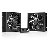
- A quiet fan kit designed for standard 19” racks, to be mounted on the roof or to replace existing fans.
- Features a speed controller utilizing PWM which can control the fan's speed without generating noise.
- Compatible with CLOUDPLATE series rack fans and can be linked to share the same programming.
- Heavy-Duty steel construction with spiral fan guards, mounting hardware, and power adapter.
- Size: Standard 120mm Rack Fans | Fans: 2 | Airflow 200 CFM | Noise: 26 dBA | Bearings: Dual Ball
Common mistakes and corrective actions
Using a thermostat reading as the IT condition
Symptom: The wall display is within 18–27°C, but a rack alarm reports high inlet temperature. Correction: Move the control reference to representative equipment inlets, inspect containment and rebalance airflow.
Controlling to RH alone
Symptom: RH looks acceptable, yet cold surfaces show condensation risk or dew point is outside the recommended envelope. Correction: Trend dew point and surface-temperature margin together with RH.
Using 70% RH without corrosion evidence
Symptom: A high RH ceiling is configured with no coupon results. Correction: Use 50% RH or lower until testing demonstrates silver below 200 Å/month and copper below 300 Å/month.
Free tools Windows power users keep installed
One-click scans. No signup required.
Treating allowable values as daily targets
Symptom: The room is intentionally operated near an A3 or A4 maximum because the equipment still runs. Correction: Return the normal target to the recommended envelope and reserve allowable conditions for managed, time-bounded operating cases.
Ignoring mixed equipment classes
Symptom: A high-density rack overheats after the room set point is widened for less restrictive equipment. Correction: Separate the zone or apply the most restrictive documented requirement.
Applying sea-level limits at altitude
Symptom: A mountain facility uses the same maximum temperature as a low-elevation site. Correction: Apply the class-specific derating above 900 m and consult the supplier above 3050 m.
Operating policy and review checklist
Record the selected targets, alarm bands and allowable excursions in the facility operating standard. At minimum, the policy should identify:
Recommended Free Tools
- Each equipment class and the OEM document supporting it.
- Recommended dry-bulb target and allowable boundary for every zone.
- Dew-point range, RH ceiling and the corrosion evidence supporting that ceiling.
- Sensor locations, calibration status, alarm ownership and data-retention period.
- Altitude, rate-of-change and noncondensing considerations.
- Conditions that permit free-cooling or other allowable-envelope operation.
- Rollback thresholds and communications steps for a cooling or humidity excursion.
Review the policy after major rack additions, cooling-system changes, containment work, a change in equipment class or any unexplained alarm pattern. The ASHRAE fifth edition is revised and expanded and covers air-cooled and liquid-cooled equipment, high-density systems and facility temperature and humidity measurement; use the applicable edition and the current OEM documentation when validating a design.
Bottom-line operating rule
Set normal control around the equipment-inlet recommendation—18–27°C for A1–A4 air-cooled equipment and 18–22°C for H1—then manage humidity with dew point, RH, corrosion evidence and a noncondensing margin. Treat the wider allowable envelope as a qualified, monitored excursion rather than a routine target. Measure where the servers actually draw air, account for altitude and change rates, and let the most restrictive installed equipment and manufacturer requirement determine the final limit.
Quick Recap
Product prices and availability are accurate as of the date/time indicated and are subject to change. Any price and availability information displayed on Amazon at the time of purchase will apply.

