
iTechGuides is reader-supported. When you buy through links on our site, we may earn an affiliate commission. As an Amazon Associate I earn from qualifying purchases. Learn more
Read a VR headset CAD reference as an engineering document, not as a picture of the headset. Before you design a mount or other accessory, verify the exact headset variant and file owner, determine whether each file is detailed mechanical CAD or a visual reference mesh, identify the real attachment surfaces and keep-out volumes, understand the coordinate frame, and test a physical prototype on the actual device. A model can look convincing and still use the wrong variant, omit hidden geometry, or place its origin somewhere that makes your measurements misleading.
Start by proving the reference matches your headset
The first design decision is not which CAD command to use. It is whether the model represents the device in your hands. Headset families often contain several variants with different shells, cameras, lens positions, adjustment mechanisms and connector locations. A reference for one model cannot be assumed to fit another simply because the products have similar names.
Record the complete device identity
Write down the manufacturer, product name, generation, variant, regional or storage edition if it changes the housing, and the hardware revision if one is available. Photograph the label or packaging and compare distinctive features such as camera windows, strap mounts, face interface, buttons and charging connectors with the CAD. If the repository names a model only in a folder title, treat that as a clue rather than proof; look for a drawing title block, readme, revision note or owner statement that identifies the same hardware.
Windows Errors? Fix Them Before They Spread
Repair common Windows errors and clear accumulated junk for a smoother, more stable PC - no reinstall needed.Free scan · no reinstallOutdated Drivers Are Slowing You Down
One free scan finds every outdated or missing driver and matches the right update for your exact hardware.Free scan · exact hardware matchDo not use user-fit specifications as housing dimensions
Meta’s comparison page, updated September 30, 2026, lists Quest 3 and Quest 3S separately. Quest 3 has continuous slider IPD adjustment, while Quest 3S has three preset IPD settings. Those facts help distinguish the products, but they are not dimensions for an accessory interface. IPD, field of view and other optical or user-fit values should never be converted into shell geometry without a drawing or a measured datum.
#1 Best Overall
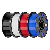
- Ender PETG Filament - combines the advantages of PLA and ABS, offering an eco-friendly, odorless, and user-friendly 3D printing experience. It features enhanced toughness that effectively resists cracking and warping, ensuring smooth and successful prints.
- Excellent Mechanical Properties - This PETG filament boasts high strength, impact resistance, and temperature resistance, with low shrinkage and high elongation at break. Printed models remain sturdy and durable even under repeated bending or stress.
- High Clarity & Glossy Finish - It delivers outstanding transparency and light transmission, making it perfect for visually detailed projects such as lampshades and display cases. The surface finishes with a smooth, glossy appearance.
- Reliable Printing & Compatibility - Dried, vacuum-sealed, and tangle-free, it minimizes clogging, bubbling, and snapping. With a precise diameter of 1.75mm (±0.02mm), it feeds smoothly and is compatible with most FDM printers on the market.
- Safe and Supported - Non-toxic and chemically resistant, Ender-PETG is safe for everyday use. Backed by Creality’s 12-month & 24 hours after-sales service. Note: Please place this product in a dry and ventilated environment, not in an environment of high temperature, sunny or humid conditions.
| Device information | What it can establish | What it cannot establish |
|---|---|---|
| Named model and variant | Which product the documentation claims to describe | That your physical unit has the same revision or shell |
| IPD or optical specification | How the user adjusts the lenses or viewing position | Housing width, camera spacing or a mounting surface |
| Photograph or marketing render | Visible features and approximate layout | Hidden ribs, wall thickness, draft, tolerances or attachment strength |
Check the owner, date and license
Prefer a manufacturer repository or a clearly identified dataset owner. Record the page title, revision or publication date and license before adapting a file. Valve Software’s official Index Hardware CAD repository, for example, states that it contains mechanical CAD for the controller, headset and base station under a Creative Commons license. The publication year is not stated on the examined repository page, so keep the repository’s current revision with your project records and verify the license terms before redistributing modified files.
Understand what each file is for
A download package may contain several representations of the same product. File extensions alone do not guarantee accuracy or intended use. Read the repository description and drawing notes before importing geometry into your CAD system.
| File or document | Typical role in a reference package | Safe design use |
|---|---|---|
| High-resolution STEP model | Parametric or solid mechanical representation intended for engineering exchange | Measure candidate interfaces and build surrounding geometry, subject to the owner’s stated scope and revision |
| Technical drawing | Dimensions, datums, section views, tolerances, notes and revision control | Use as the authority for critical dimensions, holes, planes and allowable variation |
| Low-resolution STL model | Documentation, visual reference or rapid inspection mesh | Check overall appearance and rough interference; do not infer manufacturing tolerance from facets |
| Readme, assembly note or interface description | Explains coordinate systems, mating parts, service limits, licenses and exclusions | Resolve ambiguities before making a mount or publishing derivative work |
Valve’s Index repository explicitly describes high-resolution STEP models, drawings and low-resolution STL models for documentation and reference. That is a useful example of why a package must be read as a set: the STL can be suitable for a visual check while the drawing supplies the dimension or datum needed for a load-bearing feature. Do not generalize this file-purpose mapping to every publisher; another repository may use different resolutions or export settings.
Recommended Free Tools
Look for missing or simplified geometry
Open the assembly tree and suppress or isolate parts one at a time. Determine whether the model includes the face interface, visor, strap hardware, buttons, camera windows, connector shells, cable exits, internal bosses and protective covers. A smooth exterior may hide a hollow shell, a clearance pocket or a moving mechanism. If a feature is absent, mark it as unknown rather than designing into the empty space.
Rank #2

- ①【PETG Filament 1.75mm】SUNLU PETG 3D Printer Filament combines the advantages of both PLA and ABS 3D printer filament, making 3D printing more convenient and easy.
- ②【Excellent Layer Adhesion】PETG filament offers excellent layer adhesion, reducing the risks of warping and ensuring smooth, strong prints with great structural integrity.
- ③【Enhanced Toughness】Known for its toughness, PETG outperforms many other filaments in durability, making it ideal for creating sturdy and resilient items that can withstand stress and use.
- ④ 【High Impact & Mechanical Strength】Stronger than standard PLA and easier to print than ABS. Our PETG filament provides excellent layer adhesion and impact resistance, preventing warping or cracking under stress. Perfect for printing functional parts, RC drone frames, or heavy-duty household tools.
- ⑤【Weather-Resistant for Outdoor Use】Engineered with robust UV and moisture resistance, SUNLU PETG maintains its structural integrity and color vibrancy over time. It is the ideal choice for outdoor planters, car accessories, and weatherproof garden fixtures that endure harsh sunlight or rain.
Meshes can also be decimated, scaled or exported with a shifted origin. Check the unit declaration and measure a dimension that is stated in a drawing. If the known dimension does not agree, stop and resolve the scale or revision problem before creating accessory geometry.
Map interfaces and keep-out volumes
An accessory needs more than a surface that appears flat. Identify how it is retained, which surface is intended to mate, what loads it can carry and which volumes must remain clear during use, adjustment and servicing.
Find the documented attachment interface
Search the documentation for phrases such as interface, mating surface, gasket, visor, mounting hole, magnet, clip, strap or accessory bay. Mark the exact contact faces and the direction of insertion. Note whether the interface is meant to be removable, whether it has a defined stop, and whether the retention method shares load across several points.
What’s actually slowing this PC down?
Pick the symptom - the matching free tool is one click away.
The Index documentation says its visor is held by four magnets and that the face gasket is magnetically removable. It also says the CAD can reproduce the gasket surface and the features needed to attach to the headset. Those details are more useful than tracing the outside of the visor: they identify a retention method and a mating surface that an accessory can be designed around.
Rank #3

- ①【PETG Filament 1.75mm】SUNLU PETG 3D Printer Filament combines the advantages of both PLA and ABS 3D printer filament, making 3D printing more convenient and easy.
- ②【Excellent Layer Adhesion】PETG filament offers excellent layer adhesion, reducing the risks of warping and ensuring smooth, strong prints with great structural integrity.
- ③【Enhanced Toughness】Known for its toughness, PETG outperforms many other filaments in durability, making it ideal for creating sturdy and resilient items that can withstand stress and use.
- ④【High Impact Strength】With its high impact resistance, PETG is perfect for printing parts that need to endure bumps and drops, ensuring long-lasting performance without cracks or breaks.
- ⑤【Robust Durability】PETG prints are robust and maintain their properties over time, making them suitable for both indoor and outdoor applications where weather resistance is a necessity.
Separate attachment space from sensor and camera keep-outs
Make a keep-out layer in your CAD project. Include every camera, tracking sensor, microphone opening, controller or button travel path, lens adjustment range, ventilation opening, connector and cable bend area named by the documentation. Extend the keep-out through the expected field of view rather than stopping at the visible camera window.
For the Index, Valve describes a front accessory volume called the frunk and provides a sensor-inclusion-zone model. Valve’s description is precise: “This model represents the volume that your design can occupy without occluding cameras or sensors.” Treat that volume as an Index-specific design aid, not as a universal headset rule. Valve also recommends routing a cable toward the side by the eye-relief adjustment knob when attaching elsewhere to reduce occlusion risk.
Account for connectors, controls and service limits
The Index frunk includes a USB 3 Type-A port rated for 1A at 5V. A powered accessory must leave the port, plug body and cable bend clear; a connector that fits in a static screenshot may collide when the visor or face gasket is installed. Do not remove surrounding plastic to gain space without understanding the consequences. Valve strongly recommends against removing the frunk plastic because it can affect sensor calibration and void warranty coverage. Valve also says components requiring a T5 driver or smaller are not user-serviceable. These are Index-specific warnings, but they illustrate the checks to make for any headset: preserve calibrated sensor structures and avoid assuming that a small fastener means a user-serviceable part.
Free tools Windows power users keep installed
One-click scans. No signup required.
Read coordinate frames instead of guessing the origin
A CAD origin is a mathematical reference, not necessarily the visual center of the headset. A pose origin may be placed between the lenses, on a lens plane, at a tracking marker or at an assembly datum. Before you position an accessory, identify the coordinate frame name, axis directions, units, rotation convention and the physical feature that defines the origin.
Rank #4

- [Excellent PETG Filament]Our PETG combines the benefits of PLA and ABS to reach Eco-friendly and odorless performance. This PETG Filament is feature in good toughness to avoid cracking and warping, enbale excellent 3D printing.
- [Toughness-enhanced PETG] Our PETG filament choose durable and strong material that delivers excellent clarity, light transmission, and a glossy finish. It is recommended to use a printing temperature of 220-250°C and a base plate temperature of 70-80°C for better printing results.
- [Tangle-Free & Neatly Wound] We ensure that every PETG filament is tightly and neatly wrapped by utilizing full mechanical winding, which effectively minimizes tangles, filament snapping, and line breakage.
- [No Clogging & No Bubbles] Our filaments are thoroughly dried and carefully vacuum sealed to protect them from moisture and dust, which ensures that there will be no issues with clogging or bubbling during printing. Our PETG is designed to be perfectly compatible with the majority of 1.75mm FDM 3D printers, especially suitable for Creality 3D Printers!
- [High Precision & Consistent Performance]Our PETG filament boasts a diameter of 1.75mm, ensuring utmost accuracy with a tolerance of only +/- 0.03mm. With strict quality control and impeccable dimensional precision, our PETG filament guarantees a smooth and steady feeding during printing.
Use pose documentation to locate the real reference
QuestNav’s mounting documentation, version 2026-2.2.0, provides a concrete example. Its “Third-Eye Pose” is centered between the lenses on the lens-surface plane, rather than at the center of the housing, front face or strap. The same documentation states that the Quest 3 lens plane is tilted 7° relative to the housing’s front face, while the Quest 3S lens plane is parallel to that face.
That observation applies to the QuestNav pose and those two models; it is not a general VR coordinate convention. If your target documentation defines a different origin, create a named construction plane and transform the accessory from that frame. Do not align a mount by eye to the visible front face when the required pose or optical relationship is tied to the lens plane.
Build a frame-check routine
- Import the reference without moving its native origin.
- Display the global axes and write down the unit system.
- Locate a documented datum, lens plane, hole center or connector face.
- Measure the angle between that datum and the housing face; record the sign and axis of rotation.
- Create a second, clearly named accessory frame only after the first frame is understood.
- Export a small test block or centerline and compare its orientation with the physical headset before designing the full part.
How do I know whether a headset CAD model is accurate enough?
No source reviewed establishes a universal CAD quality grade or tolerance value for VR headsets. Accuracy is adequate only for a particular design task and only when the evidence supports the dimensions that matter. A visual mesh may be sufficient for checking whether a logo is hidden, but not for locating a press-fit clip.
Quick wins for a faster PC:
Clear out junk files and repair common Windows errorsFree Scan →Scan for outdated or missing drivers - takes under a minuteDriver Scan →| Evidence to find | Why it matters | Action if it is absent |
|---|---|---|
| Exact model, variant and revision | Prevents designing against a sibling product or older shell | Contact the manufacturer or dataset owner and identify your physical unit by measurements and photos |
| Drawing with datums and tolerances | Defines the authoritative dimensions and allowable variation | Use the model only for layout; measure the mating feature on the device |
| Stated file purpose and resolution | Distinguishes engineering geometry from a display mesh | Do not use an unlabeled or visibly faceted mesh for a critical fit |
| Coordinate-frame definition | Prevents errors caused by a shifted origin or lens-to-housing angle | Create your own measured frame and document the transformation |
| Documented interface and keep-outs | Shows where attachment is allowed and what must remain unobstructed | Design a non-contacting prototype and validate sightlines and movement physically |
Use the strictest evidence required by the most sensitive feature. If a camera opening, lens relationship, connector or latch controls success, that feature needs a drawing dimension or a measurement from the actual unit even when the rest of the model is excellent.
Best Value

- High Performance & Strength: PETG filament combines the strengths of PLA and ABS. It offers low shrinkage, high impact resistance, excellent temperature resistance, and high elongation at break, models can bend repeatedly and remain firm and sturdy
- High Transparent & Glossy: PETG has a high degree of transparency. The finished product has a fine surface with exquisite details. This makes PETG material ideal for making transparent parts and models, such as lampshades, display boxes, and more
- Non-toxic Material: Creality CR-PETG 3D printing filament has excellent wether resistance and chemical resistance, no odor, and non-toxic, green environmental protection
- Wide Compatible: CR-PETG filament is wildly used in FDM 3D printers on the market.Compatible with most popular 3D printers such as MK3, Creality Ender series/CR series, ELEGOO, Anycubic, and more
- Creality Support: Creality provides 12-month & 24 hours after-sales service. Note: Please place this product in a dry and ventilated environment, not in an environment of high temperature, sunny or humid conditions
A practical workflow before you design the accessory
- Inventory the headset. Record the exact model, variant, hardware revision, strap and face interface installed, and any third-party parts that change the envelope.
- Preserve the source package. Save the original archive, readme, drawings, revision information and license. Work on a copy so that imported geometry and unit conversions are traceable.
- Classify every file. Label each item as solid CAD, drawing, mesh, assembly reference or documentation. Note missing parts and simplified regions.
- Verify units and one known dimension. Measure a drawing-controlled feature in the imported file. Correct scale only after you know whether the export or your CAD document is responsible.
- Establish datums and frames. Name the lens plane, housing face, interface plane and any pose origin. Record offsets and rotations instead of burying them in an unlabelled transform.
- Trace the interface. Model the real mating faces, magnet or clip locations, insertion direction and retention envelope. Avoid using a decorative exterior surface as a substitute for an interface.
- Create keep-out volumes. Represent camera and sensor sightlines, button travel, IPD or lens movement, connector bodies, cable bends, vents and the face or strap interface.
- Design for adjustment and assembly. Simulate installing the accessory, removing the gasket or visor where applicable, plugging cables and operating controls. Include tool access and service restrictions.
- Make a low-cost test piece. Print only the interface and the critical clearance features first. Add witness marks or measurement datums so you can identify where the fit differs.
- Test on the actual headset. Check fit, retention, camera views, controls, cable strain, lens or strap movement and comfort under realistic movement. Record changes and update the CAD revision.
Prototype checks that catch the expensive mistakes
Check static fit without forcing the shell
Install the prototype using the intended sequence. It should seat against the documented interface rather than a flexible cosmetic panel. Look for rocking, uneven contact, gaps and marks that indicate a concentrated load. Do not use tightening force to make a wrong shape fit; excessive force can deform the housing or damage a face interface.
Check tracking sightlines while moving
Inspect every camera and sensor from the angles the headset uses during operation. Then walk, turn, look up and look down while monitoring tracking. QuestNav’s mounting guide states that cameras need a clear view of environmental features and that blocking them reduces available features and degrades tracking. Its procedure calls for clear sightlines and testing under realistic movement. That advice is specific to its Quest mounting application, but the validation principle applies broadly.
Check cables, controls and adjustment ranges
- Insert and remove every connector with the accessory installed.
- Verify that a cable can bend without pulling the port or rubbing a sharp edge.
- Operate buttons, eye-relief controls, IPD adjustment and strap hardware through their full travel.
- Confirm that the face gasket, visor and other removable parts can still be installed and removed.
- Inspect the accessory after repeated movement for whitening, cracks, loose fasteners or migration.
Control clamping pressure
QuestNav warns that overtightened zip ties can strain or deform the housing and recommends securing the mount without excessive pressure. Use that warning as a design check, not as a universal fastener specification. Spread loads over a suitable interface, provide a positive stop and verify that retention does not depend on squeezing a thin shell.
Choose a prototype material for the actual test
Material choice affects stiffness, creep, surface damage and how faithfully a printed part holds its dimensions. QuestNav lists PLA+, PETG or CF-Nylon as materials recommended for durability and rigidity in its mount context, and recommends avoiding ABS for mounts in its competition vibration and impact environment. Those recommendations do not prove one filament is best for every headset accessory, printer or climate. For a first fit-check prototype, PETG is a reasonable option to consider when your printer handles it, while a final part may require a different material, inserts or a manufactured process.
If you do not own a printer, QuestNav suggests contacting local teams, school engineering departments or makerspaces. Provide the exact headset model, the intended material, the critical dimensions and the prototype’s purpose so the service can help you choose a process. A printed fit-check is evidence about one physical unit; it is not a substitute for documenting the interface and validating a production tolerance.
Common failure modes and fixes
| Symptom | Likely cause | Correction |
|---|---|---|
| The mount fits one headset but not another in the same product family | Variant or revision mismatch | Reconfirm the model identity and compare camera, lens, strap and connector features before editing the design |
| A STEP model and a printed shell disagree | Wrong units, revision, simplified geometry or undocumented physical variation | Check a drawing-controlled dimension, then measure the critical feature on the actual unit |
| The accessory blocks tracking only during head movement | Keep-out checked from one view rather than across the camera field of view | Expand the sensor and camera envelope and repeat the test under realistic motion |
| The accessory appears aligned but the optical result is wrong | Origin placed at the housing face instead of the lens or pose frame | Use the documented frame, record the lens-to-housing angle and rebuild the transformation |
| Controls or cables become difficult to use | Connector body, cable bend or control travel omitted from the envelope | Model the complete plug and bend radius, then simulate installation and operation |
| The housing shows marks or distortion | Clamping load concentrated on a thin shell or zip ties overtightened | Spread the load, add a positive stop and reduce retention pressure |
| The design relies on removing a calibrated cover | Clearance was gained by ignoring service and sensor guidance | Redesign around the documented interface; follow the owner’s warranty and service warnings |
Is there a CAD file for my VR headset?
Sometimes, but availability is model-specific. The official Valve Index repository demonstrates that a manufacturer may publish mechanical CAD, drawings and reference meshes. The reviewed sources do not establish that every commercial headset has downloadable CAD, nor that a file found online is current or dimensionally exact. Search the target manufacturer’s developer, support or hardware-documentation pages first, then ask the manufacturer or dataset owner for the current drawings, license and interface definitions when no authoritative package exists.
When only a third-party mesh is available, use it for visual planning and make the critical interface from measurements of your own headset. Mark the mesh as reference-only in the project so a later designer does not mistake it for controlled mechanical geometry.
Do these 3 things before closing this tab:
1Clear out junk files and repair common Windows errors2Fix the driver behind crashes, sound loss and screen glitches3Repair Windows errors before they cause bigger problemsQuick Recap
Release checklist for a headset accessory
- The headset model, variant and revision are written in the project metadata.
- The source owner, revision date and license are stored with the CAD.
- Each file’s purpose and resolution are documented.
- Critical dimensions come from drawings or measurements, not visual scaling.
- Coordinate origins, axes, lens planes and transformations are named.
- Attachment faces, retention features and installation direction are explicit.
- Camera, sensor, connector, cable, control, vent and adjustment keep-outs are represented.
- The prototype fits the actual device without damaging or deforming its housing.
- Tracking, controls, cables, face interface and adjustment ranges work during realistic movement.
- Any remaining uncertainty is stated in the design record and resolved before production.
Product prices and availability are accurate as of the date/time indicated and are subject to change. Any price and availability information displayed on Amazon at the time of purchase will apply.

