
iTechGuides is reader-supported. When you buy through links on our site, we may earn an affiliate commission. As an Amazon Associate I earn from qualifying purchases. Learn more
Plan a co-packaged optics (CPO) switch as a tightly coupled electrical, optical and thermal system. CPO shortens the electrical path between the switching ASIC and optical engines, which can reduce link power, but it also concentrates several heat sources in one package. The practical workflow is to define a consistent system boundary, build typical and worst-case power budgets, select a cooling architecture that fits the package and facility, then validate the complete assembly under traffic and ambient extremes.
There is no universal CPO wattage, temperature setpoint or cooling method. Published numbers apply to particular designs and comparison boundaries. Use them to size and challenge a design, not as a substitute for switch- and optical-engine vendor limits.
What CPO changes—and what it does not
In a conventional switch, optical transceivers are distributed across front-panel cages and connect to the switch ASIC through relatively long high-speed electrical traces and host SerDes links. CPO places optical engines beside, or in the same package area as, the ASIC. The shorter electrical distance can reduce signal-loss compensation and the associated energy.
Quick wins for a faster PC:
Fix the driver behind crashes, sound loss and screen glitchesFind Drivers →Clear out junk files and repair common Windows errorsFree Scan →The thermal consequence is concentration. The ASIC, optical engines, laser sources and package power-delivery components occupy a small area, so local heat flux and thermal coupling can be higher even when the switch’s total energy per bit falls. Fans, pumps, power converters and facility heat-rejection equipment still have to remove almost all electrical energy ultimately consumed by the system. CPO is therefore a change in where heat is generated and how it must be conducted, not an exemption from thermal design.
#1 Best Overall
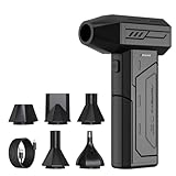
- Powerful Turbo Fan:CAGIWIRU Electric Air Duster have reached speed up to 130000RPM,Can efficient remove dust and debris.With LED light and Three Adjustable Speed to meet with different cleaning tasks.
- With Attached USB C Fasting Charging cable.Charing 3 hours,Enjoy up to 240 minutes of use on the lowest setting, For third speed can use for 25mins.with four charging options to meet with your needs.
- Wide Application:Upgraded attached 5 different nozzles,making it suitable for a variety of scenes, such as car,pet, pc, keyboards, and other electronic devices. It also serves for office and home clean duster.
- Handy Design & Portable:Cordless air duster electric nozzle is Light weight and small size, design and comfortable to hold and space saving, convenient to carry around. You can put it in your room or inside the car without taking up space.
- Warranty & Support: Our Electric air duster comes with 5 years warranty and 24/7 customer service. During this period, if you have any questions,pls kindly feel free to contact us.
“Co-packaged engines will require some sort of thermal management, either a conduction path to remove heat or to isolate the engine from other heat-generating components.”
Optical Internetworking Forum, OIF-Co-Packaging-FD-01.0, section 7.4.1 (2020)
The OIF framework discusses the requirement in the context of system integration; it is not a product specification or a universal temperature limit. Read the complete framework at OIF-Co-Packaging-FD-01.0.
The Tool Desk
Outbyte PC Repair FREEClear out junk files and repair common Windows errorsFree Scan →Outbyte Driver Updater FREEScan for outdated or missing drivers - takes under a minuteDriver Scan →Start with a defensible system boundary
Power comparisons become misleading when one design is reported at the optical module and another at the wall plug. Write the boundary at the top of the design document and keep it unchanged in every comparison. At minimum, identify whether the figure includes the host SerDes, optical engines, laser sources, fans or pumps, power supplies, voltage-conversion losses and rack or facility cooling overhead.
Record the configuration
- Switch bandwidth, ASIC or NPU model and number of ASICs.
- Number and type of optical engines, lanes, lasers and wavelength-control electronics.
- Traffic pattern, port utilization and the distinction between representative and maximum traffic.
- Airflow direction, fan redundancy, inlet-temperature range and allowable altitude.
- Power-feed redundancy, conversion stages and whether auxiliary shelves are included.
- Facility conditions: chilled-water temperature, dry-cooler capability, room air temperature, humidity and available rack heat-rejection capacity.
Separate three ledgers: power inside the switch package, power at the equipment input, and facility energy required to reject that heat. A design can improve the first while adding pumps, heat exchangers or controls in the latter two.
Build typical and worst-case power and heat budgets
Request maximum and representative power for every heat source. Include the ASIC, each optical engine, laser sources, retimers or control devices, fans or pumps and every power-conversion stage. Create at least two scenarios: normal operation at the expected traffic mix and a worst case combining maximum traffic, maximum configured optics, high inlet temperature and the permitted voltage range.
Rank #2

- Screen Cleaner is Your Screen’s New Bestfriend! - EVEO is proud to present a screen cleaner that’s perfectly suited for your TV. Meet your new screen cleaner, computer screen cleaner, laptop cleaner, iPad cleaner, Macbook,tv cleaner or any other electronic device. Our screen cleaner spray and wipe along with the included plush microfiber cloth, easily removes dust, fingerprints & other smudges on the screen’s surface. Clean effectively for a streak-free screen
- Gentle on your Screens - Our screen cleaner spray and wipes is compatible to be used even for the most sensitive LCD, LED, CRT, and OLED screens in proper use. Be at ease knowing that this product is compatible with all the major brands: LG, SONY, Samsung, Sharp, iPad, iPhone, Android screens, Kindle, PC monitors - we’ve got you covered! Can be used as LCD screen cleaner, tv cleaner, smart tv screen cleaner, and more
- Premium Super Soft Plush Microfiber Cloth - Included in this efficient screen cleaning kit. This screen cleaner spray and wipe has our signature plush microfiber cloth specially designed to comply with screens and monitors and leave them streak-free. Has been shown to effectively absorbs stubborn stains, zero streaks, and no fiber shedding. Always use this together with our screen cleaner for the best results
- Easy-to-Use Screen Cleaner Kit + microfiber cleaning cloth - The EVEO Screen Cleaning Kit will easily be your new favorite tool when it comes to taking care of the things you love most, quick and easy solution for a streak-free screen. Simply screw on the sprayer gun on the screen cleaner bottle. Spray the cleaning liquid onto the microfiber cloth, then wipe the screen until desired cleanliness & shine is achieved.
- Quality Screen Care Kit Worth Purchasing - Enjoy a convenient Screen Cleaner anytime, anywhere you need it. Your satisfaction is our top priority. We stand behind the quality of our products and that’s why, you shouldn’t be worrying at all. We manufacture the Best Screen Cleaner. and can be used for laptop cleaning kit, laptop screen cleaner, tv screen cleaner for smart tv. MacBook screen cleaner, monitor cleaner or screen cleaner spray for electronic devices with microfiber cleaning cloth
For a first-order thermal budget, treat consumed electrical power as heat that must eventually be rejected. If a component receives 600 W and has no significant stored-energy mechanism, the cooling system should be sized for approximately 600 W of heat from that component, plus the rest of the assembly. State explicitly whether your number is package-only, switch-input or facility-inclusive.
Published reference values
The OIF framework gives a representative 12.8 Tb/s, 1RU switch example. Its values illustrate accounting, not a CPO product rating:
| Item | Published value | Qualification |
|---|---|---|
| NPU power | 432 W | Representative 12.8 Tb/s 1RU switch example in the OIF 2020 framework |
| 32 optical ports | 384 W | 32 400G QSFP56-DD ports at 12 W each in the same example |
| Total consumption | 900 W typical; 1,500 W worst case | Includes fans, power supplies and typical optical dissipation for that described switch |
Do not label the 900 W or 1,500 W figures as CPO limits: the example is a representative pluggable 1RU system. Use the source table to check whether your own budget has omitted a category. The full framework is available from the Optical Internetworking Forum.
Keep comparison scope visible
A 2026 analysis by Alan F. Evans reports 23% and 67% CPO optical-transceiver energy-efficiency improvement relative to LPO and DSP transceivers, respectively. When host SerDes is included, the reported improvements are 44% and 69%. The same paper estimates switch-power reductions of 18% versus LPO links and 36% versus DSP links. These percentages depend on the components, technology generation and boundary selected by the paper.
Evans warns that “Reported power consumption savings vary greatly and there is ambiguity about what is included and what generation of technology is used.” Treat the figures as bounded results for the definitions in the Journal of Lightwave Technology article, not as guaranteed savings for an unspecified switch. When making your own table, show separate columns for optical-transceiver power, host-SerDes power, switch power and total equipment input.
Recommended Free Tools
Translate watts into cooling requirements
Cooling selection starts with heat-removal capacity, then checks temperature, reliability and service constraints. Sum the maximum heat from the ASIC, optics, lasers, memory, regulators and conversion losses. Add fan or pump electrical power because it also becomes heat somewhere in the system. Apply the vendor’s derating rules at the highest inlet or coolant temperature, rather than sizing only for a room-average condition.
Rank #3

- 【Large size】:Measuring 800 x 300 mm/ 31. 5×12 inches, which is wider and taller than others. Large mouse pad can perfectly fit your keyboard and mouse of any size, and there is also ample space for peripherals such as phones, tablets, etc.
- 【LED backlight mouse pad】:Blade Hawks RGB mouse pad provides 7 static modes and 7 dynamic modes will give you the options you are looking for. Power-off memory function remembers the last lighting mode you selected. The super glow fiber Chroma will give you a colorful gaming setup that you want.
- 【Anti-slip rubber base】:Made from Natural rubber, this gaming mousepad will firmly grip your desktop, allowing you to enjoy the ultimate precision in the games you are most passionate about. It also comes with a texture that enhances this ability even further.
- 【Smooth and waterproof surface】: Micro-textured cloth surface, for extremely precise mouse control and a smooth movement. When liquid splashes on the gaming mouse pad, it forms water droplets and slides down. Will not delay your work or gameplay.
- 【Plug and play】: This mouse and keyboard pad is powered by USB, plug and play, no driver required. One button control light modes. Press one time to change the lighting mode, press twice to change the brightness, press and hold about 3 seconds turn ON/OFF.
Air-side calculation
For air cooling, the useful capacity depends on airflow, air density, specific heat and allowable air-temperature rise. Your thermal model should use the manufacturer’s actual fan curve and account for filter loading, cable obstruction, altitude and fan-failure states. A high airflow number without the associated pressure and temperature-rise conditions is not a capacity rating.
Liquid-side calculation
For liquid cooling, capacity depends on coolant flow, specific heat, inlet temperature and permitted coolant rise. Record cold-plate pressure drop, pump operating points, quick-disconnect losses, leak detection and the heat exchanger’s approach temperature. Determine whether the facility can absorb the rejected heat at the required supply temperature; a cold plate does not eliminate a data-center heat-rejection requirement.
Design for operating envelopes, not a single point
- Normal traffic at the expected inlet or coolant temperature.
- Maximum traffic with every optical engine active.
- High ambient or warm coolant at the facility design limit.
- Fan, pump, power-feed or cooling-loop redundancy states.
- Startup, restart and control-transient conditions.
Set alarms below the vendor’s maximum ratings and leave control margin for sensor error, fouling and aging. The reviewed sources do not establish a universal CPO junction-temperature setpoint; that value must come from the component and package suppliers.
Windows Errors? Fix Them Before They Spread
Repair common Windows errors and clear accumulated junk for a smoother, more stable PC - no reinstall needed.Free scan · no reinstallCrashes, No Sound, or Screen Glitches?
Random freezes, missing sound and display glitches usually trace back to one bad driver. Find and replace yours safely.Free scan · under a minuteCompare cooling architectures before freezing the package
Four architectures commonly appear in CPO discussions. Their suitability depends on heat density, service model and facility readiness, not on a single efficiency claim.
| Architecture | Strengths | Risks and dependencies | Design implications |
|---|---|---|---|
| Air cooling | Familiar infrastructure, relatively low cost and compatibility with hot-swappable fan arrays | Lower cooling efficiency, acoustic output and limited capacity as local heat flux rises | Requires careful heatsink, airflow-path and obstruction design; validate fan-failure operation |
| Closed-loop liquid | Higher heat-removal capacity than air and quieter operation | Pump reliability, seals, controls and added cost; the OIF framework described data-center deployment as limited when written | Needs cold plates, coolant monitoring, a heat exchanger or radiator and service procedures |
| Open-loop liquid | Greater capacity in the OIF comparison | External flowing-liquid supply, heat exchanger and facility dependency; one supply failure can affect multiple units | Requires plumbing, isolation, leak detection, water-quality control and coordinated maintenance |
| Immersion | Potentially high capacity and equipment density | Fluid and pump reliability, hermeticity for optics and fiber connectors, major redesign and cost | Requires fluid compatibility qualification, tank or bath redesign, service tooling and a new deployment model |
These descriptions are the baseline comparison in the OIF framework, not a current vendor survey or an endorsement. Evaluate each option against the following gates:
- Capacity: Can it remove the worst-case heat with margin at the facility’s hottest condition?
- Temperature: Do ASIC, optical-chip, laser and connector limits remain satisfied, including gradients and transients?
- Reliability: What happens after a fan, pump, valve, power feed or facility loop failure?
- Infrastructure: Are plumbing, heat exchangers, leak detection, power and controls available at the rack?
- Serviceability: Can technicians replace a switch without draining a loop or disturbing neighboring units?
- Noise and density: Are acoustic and rack-density targets compatible with the chosen method?
- Cost and maturity: Include capital equipment, operating energy, spares, training and redesign.
Control thermal coupling inside the package
Sharing package area makes the ASIC and optical engines thermal neighbors. Heat flowing through a common substrate, lid or heatsink can raise optical-chip temperature even when the optical engine is not the largest electrical load. Conversely, a hot ASIC can create a local gradient that affects laser stability or optical performance.
Rank #4

- 【Softer and More Comfortable】Vaydeer wrist rest has unique diamond pattern, which is the combination of softness and aesthetics. The materials of wrist rest are improved into higher quality memory foam and covered with silky smooth lycra. The computer wrist rest makes you as comfortable and cushiony as like rest your wrists on clouds.
- 【Ergonomic Wrist Saver】The wrist rests for keyboard and mouse comes with a 17.32×3.15×0.83 inch keyboard wrist pad and a 5.94×3.15×0.83 inch mouse wrist support. Based on ergonomic design, the unique concave shape is the perfect fit for your wrist joints. The wrist rest pad fits most computer keyboards and laptops, improve hand and wrist posture, release your wrist and arm stress.
- 【Non-Slip Rubber Bottom】Featuring an anti-skid silicone base on the bottom, this wrist keyboard support stays firmly in place on your desk, preventing the padding from sliding around, ensuring stable and consistent wrist support during extended computer sessions.
- 【Better Experience & Pain Relief】Our keyboard arm rest is beneficial to alleviate the soreness caused by direct contact and friction between your arm and a hard desk surface, reducing the risk of wrist fatigue or carpal tunnel. The soft texture of memory foam can evenly distribute the pressure around your wrists and provide good support with just enough give.
- 【Helpful in Multiple Scenarios】Whether you're working, studying, writing, typing, gaming, this keyboard and mouse rest combo is an essential accessory to add comfort and support to your hands and wrists. It’s also a great gift for men, women, family, friend, coworker, gamer, teacher, etc.
An IEEE Photonics Technology Council presentation identifies several design levers: separate heat paths for ASIC and optics, heatsinks with more surface area, directed airflow, suitable thermal-interface materials and thermally conductive package vias. The correct combination depends on package geometry, component limits and the system cooler; the presentation does not validate one switch design. Review the technical discussion in the IEEE Photonics Technology Council presentation.
What to model
- Steady-state junction, case and optical-chip temperatures for every heat source.
- Thermal resistance and capacitance from each die to the cooler and between neighboring dies.
- Temperature gradients across laser and optical-engine regions.
- Interface-material thickness, compression, pump-out and aging effects.
- Transient response during traffic steps, fan-speed changes and cooling-loop disturbances.
Do not use one measured ASIC temperature as proof that every optical engine is safe. Place sensors at the package hot spots and correlate them with calibrated thermal simulations and vendor limits.
Use laboratory results correctly
A 2024 IEEE conference paper reports a liquid-cooled CPO design tested at 290 W input power. In that experiment, the ASIC junction reached 51 °C, optical-chip temperatures were 28 °C to 29 °C, and the maximum difference among the optical chips was 0.6 °C. Those are results for that paper’s package, cooler, test conditions and instrumentation—not standard targets for every CPO switch.
Use the result as a validation pattern: identify input power, coolant conditions, sensor locations, thermal gradients and workload before comparing it with your design. The paper is available at IEEE Xplore.
Independent reader supportYour contribution helps us test, update, and keep practical guides available for everyone.Request the data that closes package-level risk
A vendor discussion should produce numbers and interfaces that can be inserted into your model. Ask the switch, ASIC-package and optical-engine suppliers for:
Free tools Windows power users keep installed
One-click scans. No signup required.
- Power by operating mode, lane rate, traffic level and laser state, including tolerance and maximum values.
- Maximum rated junction, case and optical temperatures, plus derating curves and shutdown behavior.
- Heat-source locations, thermal-resistance data and allowable thermal gradients between ASIC and optics.
- Cold-plate or heatsink contact requirements, flatness, mounting force and thermal-interface-material specification.
- Liquid type, allowable inlet temperature, flow range, pressure drop, cleanliness and leak-test requirements.
- Airflow direction, minimum flow, pressure curve and fan-failure behavior if air cooled.
- Optical penalties or protection behavior during temperature excursions, pump loss and fan-speed reduction.
- Connector, fiber and hermeticity limits for any immersion or liquid-adjacent design.
- Telemetry points, alarm thresholds, firmware controls and safe-state behavior.
If a supplier cannot provide a value, mark it as an open project input and assign a validation test. Do not silently substitute a number from another package or from a laboratory demonstration.
Best Value

- 【No Drill Mounted】Cable management tray can be assembled in as little as 3 minutes or less-simply. Side clips easily clampe the edge of desk, pass through the holes on the sides, and secure excess cables with baskets. Desk cable management supports inward or outward installation to meet your needs in different scenarios, and provides you with great convenience when collecting and organizing wires.
- 【Rubber Pad Protects Desk】Wire organizer under desk built-in soft rubber pads on the clamp protect your desk from scratches, so you will not damage your furniture or office.
- 【Sturdy and Beautiful】Cord management under desk is made of high-quality carbon steel and holds about 15 lbs. The wire basket has 2 holes on each side of the tray to enable your cables to pass freely. Cable baskets are suitable for desk thickness use from 0.4" to 2.4".
- 【Space Saving & Keep Organized】Desk cable management tray holds all your power cords, outlet strips, USB hubs and computer transformers hidden from your feet, and the data cables will not enter the vacuum cleaner to keep your desk clean and tidy. Desk wire organizer is also suitable for use in the kitchen and outdoors.
- 【Reduce Safety Risks】Cable tray under desk keeps all plugs away from your kids, no more worry about tripping. Using 2 holes wire tray saves extra space, helps you easily cabling and wire protection. The mesh design is not easy to accumulate dust, but avoids safety accidents caused by messy wires.
Validate the complete switch and facility envelope
- Instrument the assembly. Measure equipment-input power, ASIC and optical temperatures, inlet and exhaust air or coolant temperatures, flow, pressure, fan or pump power and ambient conditions.
- Establish a baseline. Run representative traffic with the normal redundancy state and record stabilized temperatures and control-loop behavior.
- Apply worst-case load. Enable the maximum optical configuration and traffic pattern while operating at the highest permitted inlet or coolant temperature.
- Exercise transients. Step traffic, change fan or pump speed, and cycle optical engines to expose thermal time constants and control overshoot.
- Test faults. Simulate a failed fan, pump, power feed, sensor and facility cooling path. Verify alarms, throttling and orderly shutdown.
- Check rack interactions. Repeat with neighboring equipment, cable fill and realistic airflow or plumbing restrictions.
- Compare model and measurement. Explain every discrepancy, update material and interface assumptions, and rerun the hot-spot cases.
- Document acceptance limits. Record measured margins to each vendor rating, not merely pass or fail at one room condition.
Facility acceptance should include the heat exchanger, secondary loop, controls and redundancy—not just the switch cold plate. A switch that survives a bench test can still exceed rack or room limits when several units share a coolant loop.
Common planning failures and how to correct them
Comparing optical modules only
Symptom: CPO appears to save a large percentage, but rack power barely changes. Correction: Add host SerDes, conversion losses, fans or pumps and the same switch configuration to both alternatives.
Using a typical value for protection sizing
Symptom: Temperatures rise during maximum traffic or hot-room operation. Correction: Maintain separate typical and worst-case budgets and size capacity for the latter with explicit margin.
Assuming a published temperature is a limit
Symptom: A design is declared safe because it matches a conference-paper temperature. Correction: Use the paper as evidence of one experiment and obtain rated limits and derating behavior from the actual suppliers.
Ignoring facility dependencies
Symptom: A liquid design meets package temperatures but cannot maintain flow or heat rejection in the intended rack. Correction: Validate pumps, heat exchangers, plumbing, water quality, leak response and maintenance procedures as one system.
Leaving no service or failure state
Symptom: A single pump, fan or sensor fault forces an immediate outage. Correction: Define redundancy, degraded-performance modes, alarms and safe shutdown before selecting the package cooler.
Quick Recap
A practical decision sequence
- Freeze the comparison boundary and configuration.
- Collect component-level typical and maximum power and temperature data.
- Build package, switch-input and facility heat ledgers.
- Model thermal coupling and identify the hottest ASIC and optical regions.
- Screen air, closed-loop liquid, open-loop liquid and immersion against capacity, temperature, reliability, infrastructure and service criteria.
- Select a provisional architecture with measurable margins and a defined failure mode.
- Prototype the package-to-cooler interface and instrument every important heat path.
- Run representative, worst-case, transient and fault tests at facility-relevant conditions.
- Approve deployment only when measured margins and infrastructure dependencies are documented.
Product prices and availability are accurate as of the date/time indicated and are subject to change. Any price and availability information displayed on Amazon at the time of purchase will apply.
What’s actually slowing this PC down?
Pick the symptom - the matching free tool is one click away.

