
iTechGuides is reader-supported. When you buy through links on our site, we may earn an affiliate commission. As an Amazon Associate I earn from qualifying purchases. Learn more
Valve published Steam Frame CAD files and electrical interface information through its Steam Hardware announcement dated October 9, 2026. To work with them, follow the announcement’s CAD-files link, inspect the package to identify the actual file types and any README, then open the files in software that explicitly supports those types. Because Valve has not identified a required application or confirmed the formats in the published material, do not assume that a particular CAD program will open them.
After import, verify the model’s units before measuring. Use the application’s native measurement and inspection tools for distances, diameters, angles and overall extents, and report those CAD measurements separately from Valve’s published product dimensions. Valve lists the core module plus facial interface at 175 × 95 × 110 mm, but cautions that specifications may change before availability.
What Valve released and what is still unknown
Valve’s Steam Hardware announcement on October 9, 2026 states: “Steam Frame CAD files and electrical interface information are now available for non-commercial use.” The announcement points readers to the files and gives commercial users separate instructions that include contacting Valve.
The release is useful for enclosure planning, accessory design, fit checks, cable routing and other engineering work. It does not, by itself, establish which CAD formats are included, how the folders are organized, which application Valve recommends, or which application-specific menu commands you should use. Those details must be checked in the downloaded package and in the software you choose.
#1 Best Overall
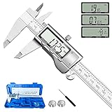
- 【STAINLESS STEEL MATERIAL】The vernier caliper is made of high-strength stainless steel and is waterproof and dirt-proof. The service life of this stainless steel digital caliper is longer than that of calipers with plastic or carbon fiber parts.
- 【ACCURATE MEASUREMENT AND ZERO SETTING】This digital caliper glides smoothly. Measuring range: 0 -6" / 0-150mm; Accuracy: ± 0.001"/ 0.02mm; Resolution: 0. 0005"/0. 01mm. At the same time, the smart design allows you to easily reset to zero by pressing a button and start a new measurement at any point on the scale, which is very suitable for differential measurement.
- 【4 MEASUREMENT MODES】The digital caliper has 4 measurement modes, which can be used to measure inside and outside diameter, depth, and step with two sets of jaws and a probe. Multiple measurement modes can bring more usage scenarios to people, and the measurement process is also very convenient.
- 【UNIT CONVERSION & LARGER LCD SCREEN】These Digital Calipers have a one-key button to quickly switch from inches (inch), fractions (F), millimeters (mm). The 6" digital caliper has a large, easy-to-read LCD DISPLAY which is easy to use and read even under strong sunlight. It will automatically turn off after 5 minutes of non-use to save power.
- 【Wide Applications】 Compared to the ordinary rulers, this stainless steel caliper can measure not only length but also caliber and depth, allows you to measure circular and cylindrical objects, more functions and better performance will satisfy you. It has always been used by professionals and hobbyists alike, jewelers, hobbyists, woodworkers, machinists, DIY, automotive mechanics, and more.
Valve’s published size reference
| Item | Published dimensions | Qualification |
|---|---|---|
| Core module plus facial interface | 175 × 95 × 110 mm | Valve product-page dimensions; Valve warns that some specifications may change before availability |
Those three numbers are an overall product reference, not a substitute for measuring a particular surface in the CAD model. They may include both the core module and facial interface, while a file may contain separate bodies, hidden construction geometry or additional parts.
Find the official files
- Open Valve’s Steam Hardware announcement dated October 9, 2026.
- Use the CAD-files link in that announcement rather than a repost, screenshot or third-party mirror.
- Read any license notice, README, folder notes and revision information before opening the model.
- Download the complete package, including any electrical-interface material and accompanying documentation. Do not copy only the first file you see; assemblies often depend on sibling files.
- Keep the original download unchanged. Make a working copy for imports, conversions and annotations so you can return to Valve’s supplied files if an import changes geometry.
If the announcement link leads to a repository, look for a release or revision identifier, a changelog and instructions about the intended use. Record the date and identifier with your measurement notes. Valve’s product page says specifications may change, so measurements made from a later revision may not match an earlier one.
Inspect the package before choosing software
The safest way to answer “Which CAD program opens the Steam Frame files?” is to inspect the actual package first. The currently published material does not identify the file formats or a required application, so a software recommendation made before inspection would be speculative.
Checklist for the first inspection
- List every file and folder, including README, license, drawing and revision files.
- Note each file’s extension and approximate size. A very small file may be a drawing, metadata record or link to another file rather than the model itself.
- Check whether there is one assembly with referenced parts or several independent bodies.
- Look for separate files for the core module, facial interface, fasteners, cable features or electrical connectors.
- Read any stated unit system, coordinate-system description, origin convention and revision date.
- Check whether the package contains a neutral exchange model, a native editable model, a polygon mesh, or more than one representation. Do not infer the exact type until the files or README identify it.
Do not rename extensions to force an import. An extension change does not convert the underlying data and can make later troubleshooting harder. If the package includes several representations, preserve each one and decide which is appropriate for measurement.
Choose an application without assuming compatibility
Select a CAD or 3D inspection application only after you know what the package contains. The application must support the identified file type and provide reliable measurement tools. If the README names a program or workflow, follow that instruction; otherwise consult the application’s documentation for the exact import method.
| What you find in the package | What to verify in the application | Measurement implications |
|---|---|---|
| An editable solid or surface model | Native import support, assembly-reference handling and unit interpretation | Usually suitable for precise edge, face, hole and distance measurements when geometry imports without repair |
| A polygonal model | Mesh import, scale handling and a tool that measures between vertices, edges or fitted features | Results depend on mesh resolution and may not represent the exact design surface |
| A drawing or 2D technical document | Ability to open the drawing and read its stated scale and units | Useful for annotated dimensions, but not equivalent to measuring 3D geometry |
| Several representations | Whether the files share the same revision and coordinate system | Compare only after confirming that the representations describe the same revision |
Before importing the Steam Frame model, open a known sample file supplied with your application. Confirm that its measurement readout, unit display and export behavior are sensible. This separates an application-configuration problem from a problem in the Valve package.
Rank #2

- Best Cost-effectiveness: We've crafted this plastic digital caliper with a singular focus – delivering unmatched value at an unbeatable price. While others chase high-precision innovations, we prioritize essential features that truly matter.
- 4 Measurement Modes and Precision: Outside diameter, inside diameter, depth, and step measurements. Measurement range: 0-6 inches / 0-150 mm, accuracy: ±0.2 mm / 0.01 inches. Whether it's for home projects, DIY, or 3D print, having this caliper will elevate you to be a measurement star.
- Low Energy Consumption Design with Smart Auto-Off Function: With just a single battery, our caliper can support 8+ months of measurements. It can automatically turns on when you slide it, and turns off within 5 mins when not in use, effectively conserving battery power.
- Tough Plastic Case Packaging and Secure Measurements: The plastic case packaging effectively protects the caliper from external impacts and friction, ensuring that it stays in optimal condition at all times. Moreover, our digital caliper is made of extra strong carbon fiber composites that are not easy to damage the measured object during use.
- What You Get: Digital Caliper *1, Tough Plastic Case *1, and LR44 button batteries *3(with one pre-installed). Additionally, we offer a lifetime warranty and friendly customer service to ensure your complete satisfaction.
Open the model safely
- Create a working copy. Leave the downloaded Valve files untouched and work from a duplicate in a clearly named project folder.
- Start the application and use its documented Open or Import command. Do not drag files into an unrelated viewer unless that viewer explicitly supports the identified type.
- Select the primary model or assembly. If the package contains linked parts, keep the folder structure intact so references can resolve.
- Accept import options only after reading their unit and scale settings. Disable automatic scaling when you need to preserve the source dimensions, unless the README specifically instructs otherwise.
- Wait for the import to finish and inspect the model tree. Confirm that expected bodies, interfaces and reference parts are present.
- Fit the model to the viewport, then isolate components. Hide construction geometry, duplicate bodies and reference planes when they could be mistaken for physical surfaces.
- Save the project in the application’s native project format. Keep the original source files attached or referenced, and record the application version and import options.
If the application reports missing references, stop and repair the folder paths before measuring. A partial assembly can produce plausible but incorrect overall dimensions.
Do these 3 things before closing this tab:
1Clear out junk files and repair common Windows errors2Scan for outdated or missing drivers - takes under a minute3Repair Windows errors before they cause bigger problemsVerify units before taking any measurement
Unit mistakes are the most common reason a correctly imported model appears impossibly large or small. A CAD viewer may display a unit label while silently applying an import scale, and a mesh viewer may treat unitless coordinates as arbitrary units.
- Open the document, project or scene-units settings.
- Check the model’s stated units in the file information or README, if provided.
- Check the application’s display units and precision separately. Displaying millimetres does not prove that the geometry was imported at millimetre scale.
- Measure a feature whose approximate scale is obvious from the model, such as the overall headset-sized body, and compare it with the 175 × 95 × 110 mm published reference without altering the source.
- If the scale is wrong, use the application’s documented unit-conversion or scale command on a copy. Record the factor, original units and resulting units in your notes.
- Reopen the converted copy and repeat the check. A scale correction that changes only the display, not the geometry, will not fix exported dimensions.
Do not round the model to the published product size to make it fit. The published figure is a reference for the core module plus facial interface; it is not evidence that every body, clearance or subassembly should have those extents.
Measure overall dimensions
Use the application’s bounding-box, overall-extents or equivalent inspection command for a first check. Menu names differ by application, so use the command documented for your software rather than relying on a guessed path.
- Hide nonphysical reference geometry and select the bodies that represent the item you want to report.
- Align the model to a meaningful coordinate system or preserve the supplied orientation. Record whether the measurement is axis-aligned or taken after rotating the model.
- Read the minimum and maximum extents along the three axes. Capture the values and the unit shown by the application.
- Repeat the measurement for the core module alone, the facial interface alone and the combined selection when those bodies are separate.
- Record which bodies were included, whether hidden parts were excluded and which revision of the Valve files was used.
An axis-aligned bounding box can be larger than the physical envelope if the model is rotated relative to its design axes. For a packaging or fit decision, document the orientation and, where appropriate, also record the smallest oriented box or the specific mating surfaces that drive the fit.
What’s actually slowing this PC down?
Pick the symptom - the matching free tool is one click away.
Measure distances, angles and circular features
Point-to-point and edge-to-edge distances
Activate the application’s distance or measure tool, select the two points, vertices, edges or faces required by the tool, and read the result in the verified unit system. State exactly what was selected: a sharp edge, a tangent point, a face center or a projected point can produce different values.
Rank #3

- [INCH/MM Conversion]: One button can quickly convert two measuring unit (INCH/MM). Measuring Range:0 - 150mm (6") / Resolution: 0.01mm (0.0005")/Accuracy: ±0.02mm (0.001")
- [Stainless Steel Material]: The vernier caliper is made of high-strength stainless steel, which is waterproof, stain-proof and oil-proof. The ergonomic design brings you a comfortable feeling.
- [Large and Clear Display Screen]: Large LCD display gives you a clear reading. The thumb rolling and locking screw provide easy sliding, accurate positioning, and fine adjustment.
- [Multifunctional Use]: The digital micrometer can easily and accurately measure internal, external, height and depth dimensions.
- [Automatically shut off]: When you have no action on the dial caliper, it can automatically shut off after 4 minutes.
Face-to-face clearances
Select opposing planar faces when the question is a wall-to-wall clearance. If the faces are not parallel, use the application’s minimum-distance or closest-point function and report that method. A visual gap in the viewport is not a measurement.
Holes, bosses and circular interfaces
Use a diameter or radius measurement on the cylindrical face or circular edge. Specify whether the value is the design diameter, the measured opening at one end, or a countersink or chamfer diameter. If the model contains threads or a faceted approximation, state that the result comes from the represented geometry rather than a manufacturing tolerance.
Angles and orientation
Measure between the two faces, edges or axes that define the angle. Record the reference coordinate system and whether the application reports the supplementary angle. For a facial interface or strap feature, an angle without its reference planes is difficult to reproduce.
The Tool Desk
Outbyte PC Repair FREERepair Windows errors before they cause bigger problemsFix Now →Outbyte Driver Updater FREEFix the driver behind crashes, sound loss and screen glitchesFind Drivers →Curved surfaces and ergonomic clearances
A single point-to-point measurement does not describe a curved surface. Use a section plane, surface-distance or curve-length tool where available, and save the section location or sketch used. For an ergonomic clearance, identify the two surfaces and the direction of the clearance rather than reporting only a viewport estimate.
Use the electrical-interface files correctly
Valve announced electrical interface information alongside the CAD files. Treat that material as a separate engineering reference unless the package explicitly links it to model geometry. An electrical drawing may define connector locations, pin assignments or keep-out areas without containing a directly measurable 3D body.
- Keep electrical documents and mechanical models under the same revision record.
- Check whether connector dimensions are nominal, maximum, recommended keep-outs or another category.
- Do not infer pin spacing or mating requirements from a visual connector model when an electrical document supplies the authoritative value.
- When creating an enclosure, combine measured mechanical surfaces with the electrical document’s stated clearances and orientation.
Compare your measurements with Valve’s reference size
Use a comparison table in your notes rather than replacing model measurements with the product-page figure.
Rank #4

- Solid stainless steel build – This digital caliper 6 inch resists rust, wear, and corrosion, outlasting plastic models. The sturdy metal body handles daily workshop use without bending. The shockproof case protects your measuring tool from drops and impacts, keeping it safe and ready for each job
- Reliable accuracy with smooth glide – This digital vernier caliper measures 0‑6″ / 0‑150mm with ±0.02mm / 0.001″ accuracy and 0.01mm resolution. The thumb roller glides without sticking, and the locking screw holds your reading steady. From checking 3D print filament and woodworking joints to measuring jewelry and small parts for repairs, you can trust the results
- Four measurement modes in one – Use two jaw pairs and a depth probe for ID, OD, depth, and step measurements. No need to switch digital caliper measuring tool – this versatile dial caliper covers tubing, bores, recesses, and shoulders. Press the zero button anywhere to reset for quick comparative checks. Close and re‑zero before each use to ensure consistent readings
- Metric & Imperial conversion with large LCD – This electronic vernier caliper lets you switch between millimeters and inches with one click. The oversized LCD screen displays crisp, bold numbers that are easy to read at a glance. The wide viewing angle means you can read it clearly without tilting the caliper. Auto‑off powers down after 5 minutes of non‑use to save battery
- Complete kit – ready out of the box – Your package includes the digital micrometer, a sturdy case, two batteries (one spare), a mini screwdriver, and a stainless steel ruler. No extra trips to the store – just open and start working. A practical choice for DIYers, hobbyists, and makers who need reliable measurements at home or in the workshop
| Check | What to enter | How to interpret it |
|---|---|---|
| Combined core module plus facial interface extents | Your measured X, Y and Z values, unit system and orientation | Compare with 175 × 95 × 110 mm, while noting that Valve says specifications may change |
| Core module alone | Measured extents and included bodies | Do not compare directly with the combined published figure unless the facial interface is included |
| Facial interface alone | Measured extents and included bodies | Use to plan removable interfaces or padding; no separate Valve overall dimension is established here |
| Internal clearances or connector features | Feature-specific measurements and selection method | These are CAD-derived values and should not be presented as Valve’s published product dimensions |
Small differences can result from selecting different bodies, including trim or padding, using a rotated coordinate system, or measuring a later or earlier revision. Investigate the selection and revision before treating a difference as an error.
Recommended Free Tools
Troubleshoot common failures
The file will not open
- Confirm that the download completed and that the file size is plausible.
- Read the README for a required import sequence or companion files.
- Restore the original folder structure so linked parts can be found.
- Check whether your application supports the identified file type and revision.
- Try a current version of the application only if its documentation confirms support; do not convert the source repeatedly, because each conversion can remove editable features.
The model is extremely large or tiny
Recheck source units, application display units and any import-scale dialog. Compare a measured overall extent with Valve’s 175 × 95 × 110 mm reference only after confirming that you selected the combined core module and facial interface.
Only part of the assembly appears
Look for unresolved references, suppressed components, hidden bodies and separate facial-interface files. Open the assembly from the supplied top-level file when one exists, rather than opening an individual part and assuming it is complete.
The model looks faceted
A faceted display may be only a viewport setting, or it may indicate that the supplied representation is polygonal. Increase display tessellation for visual inspection, but do not claim greater dimensional accuracy than the underlying geometry supports.
The measurement tool is unavailable
Some viewers can display a model but cannot measure it, while others require an inspection or analysis workspace. Consult the application’s documentation for its measurement feature. If the file is a drawing, use its annotated dimensions and stated scale rather than pretending it is a 3D measurement.
Quick wins for a faster PC:
Clear out junk files and repair common Windows errorsFree Scan →Fix the driver behind crashes, sound loss and screen glitchesFind Drivers →Measurements change after export
Compare the source and exported copies using the same unit system and the same selected bodies. A conversion may change tolerances, heal gaps or tessellate surfaces. Keep the source measurement as the baseline and identify the conversion tool and settings in any report.
Best Value
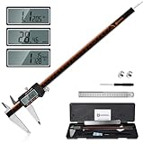
- 【Stainless steel material】Digital calipers are made of high quality stainless steel, waterproof and rustproof, and the sturdy frame reduces the wear and tear of vernier calipers, allowing a longer service life
- 【Accurate measuring range】 0-12 inches/300mm; Display: 14mm x 40mm oversized LCD; Accuracy: ±0.04mm/0.0015 inches; Resolution: 0.01 mm/0.0005 inches. The knurled thumb roller ensures smooth gliding in use; the locking screw enables accurate positioning. These two designs ensure smooth operation during measurement and prevent slippage or jams from occurring
- 【4 measurement modes】The digital caliper comes with two pairs of jaws and a probe to easily measure depth, step length, outside diameter and inside diameter. Four measurement methods meet most of your measurement needs
- 【3 unit conversions】 With the push of a button, you can quickly switch between the 3 units of the digital caliper: inches, millimeters and fraction; plus the large LCD screen makes it easy to read. You can reset it to zero with the zero button, plus the digital vernier caliper will automatically turn off after 5 minutes of non-use to save power
- 【Wide application】HARDELL digital caliper comes with 1*ruler, 1*screwdriver, 2*batteries. The case is resistant to pressure, shock and drop for easy storage and carrying. 12 inch caliper micrometer has been used by professionals and amateurs, it is the best choice for mechanics, woodworkers, jewelers, craftsmen, DIY enthusiasts, auto mechanics, etc
Report measurements so someone else can reproduce them
A useful measurement record contains more than a number. Include:
- Valve file name, revision or download date.
- Application name and version.
- Import method and any scale or unit setting.
- Selected bodies, hidden bodies and coordinate-system orientation.
- Measurement tool and selected geometric entities.
- Displayed unit, decimal precision and any rounding.
- Screenshots showing the selection and result when the value affects a design decision.
- A note distinguishing CAD geometry from a physical sample and from Valve’s published product-page dimensions.
For collaborative work, save a copy of the application project and an export of the measurement report. Preserve the untouched Valve files so a later revision can be compared without ambiguity.
Commercial-use warning
Valve’s announcement specifies non-commercial use for the released Steam Frame CAD files and electrical interface information. It directs commercial users to follow its linked instructions and contact Valve. If your work involves selling a product, paid design services, manufacturing for a customer or another commercial activity, review Valve’s instructions and obtain the necessary permission before relying on the files.
Free tools Windows power users keep installed
One-click scans. No signup required.
Non-commercial availability does not remove ordinary responsibilities such as checking revision status, validating fit on physical hardware and observing any separate electrical or safety requirements. A CAD measurement is an aid to design, not a guarantee that a fabricated part will fit every production unit.
Practical stopping point
You have a defensible result when you can identify the exact Valve file revision, show that the assembly is complete, demonstrate the unit check, name the bodies and geometric entities measured, and state whether the number came from the CAD geometry or from Valve’s published 175 × 95 × 110 mm reference. Until the repository confirms its formats and workflow, the correct software choice remains conditional on what the package actually contains.
Quick Recap
Product prices and availability are accurate as of the date/time indicated and are subject to change. Any price and availability information displayed on Amazon at the time of purchase will apply.

