
Recommended Free Tools
iTechGuides is reader-supported. When you buy through links on our site, we may earn an affiliate commission. As an Amazon Associate I earn from qualifying purchases. Learn more
To make a straight-through Ethernet patch cable, use twisted-pair patch cable and RJ45 plugs designed for that cable, arrange all eight conductors in either the T568A or T568B order, and terminate both ends with the same scheme. Crimp with a connector-compatible tool, then use a wire-map tester to check that pin 1 reaches pin 1 through pin 8 reaching pin 8. A basic wire-map pass confirms termination and continuity; it does not certify category performance or guarantee gigabit, 10-gigabit, Power over Ethernet, or any other data rate.
What you are making
A normal patch lead is a straight-through cable: each conductor terminates on the same numbered pin at both ends. You choose one recognized color scheme—T568A or T568B—and repeat it at the far end. The two schemes differ only in the positions of the orange and green pairs. If one end is T568A and the other is T568B, the result is a crossover cable, not the straight-through cable this guide describes. See the wiring comparison from Fluke Networks.
Modern network ports often accommodate either cable type automatically, but there is still no reason to make a crossover cable accidentally. Matching the same pattern at both ends makes the intended wiring unambiguous and easier to troubleshoot.
The Tool Desk
Outbyte Driver Updater FREEScan for outdated or missing drivers - takes under a minuteDriver Scan →Outbyte PC Repair FREEClear out junk files and repair common Windows errorsFree Scan →Materials and tools
Gather the following before cutting the cable. Compatibility matters more than buying the most expensive tool: the plug must accept the cable’s conductor type and size, and the crimper must be made for that plug style.
#1 Best Overall
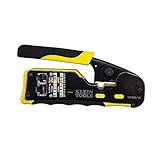
- EFFICIENT INSTALLATION: Modular crimp-connector tool with Pass-Thru RJ45 plugs for voice and data applications, streamlining installation process
- VERSATILE FUNCTIONALITY: Wire stripper, crimper, and cutter in one tool, designed for STP/UTP paired-conductor data cables
- PRECISE TRIMMING: Flush trimming to connector end face to prevent unintended contact between conductors, ensuring optimal performance
- COMPATIBLE CONNECTORS: Crimps and trims Klein Tools RJ45 Pass-Thru Connectors, providing reliable and secure connections
- WIDE COMPATIBILITY: Supports crimping of 4, 6, and 8 position modular connectors, including RJ11/RJ12 standard and RJ45 Klein Tools Pass-Thru
| Item | What to select | Why it matters |
|---|---|---|
| Twisted-pair Ethernet cable | A category-rated patch cable with four twisted pairs; stranded patch cable is the focus of this procedure. | The conductor diameter, insulation, and stranded or solid construction determine which modular plug will make a reliable contact. |
| RJ45 modular plugs | Plugs specified for the cable’s conductor type, gauge range, insulation diameter, and category. | A plug intended for a different conductor construction may not grip the contacts or jacket correctly. |
| RJ45 crimping tool | A crimper explicitly compatible with the chosen plug family. | Crimp geometries differ. A generic tool may not seat contacts or strain relief correctly. |
| Wire-map tester | A tester with a main unit and detachable remote for eight-conductor Ethernet cable. | It can identify common opens, shorts, crossed conductors, and other mapping errors after termination. |
| Cable stripper or jacket cutter | Use one only if your plug or tool instructions call for it. | Strip-back length and method vary by connector design; excessive stripping exposes or untwists too much cable. |
The Leviton EZ-RJ45 instructions illustrate a product-specific plug and tool process. Treat those strip lengths, insertion details, and crimp steps as instructions for that connector, not as universal dimensions for every RJ45 plug.
Choose the right cable and plug combination
Use patch cable for a short patch lead
This how-to is for a flexible patch cable, normally made with stranded conductors. Select cable and plugs sold or specified as a matching system. Category labels alone do not prove that any plug fits any cable; conductor gauge, insulation diameter, and construction are separate constraints.
Do not mix bulk in-wall cable casually
Bulk horizontal cable is commonly solid-conductor cable intended for fixed installation and punch-down hardware. A plug designed for stranded patch cable may not make a dependable connection to it, and a plug intended for solid cable may not suit a flexible stranded lead. If you need to terminate solid cable, follow the plug manufacturer’s exact specification for that conductor and use the corresponding connector and tool.
Do these 3 things before closing this tab:
1Scan for outdated or missing drivers - takes under a minute2Repair Windows errors before they cause bigger problems3Fix the driver behind crashes, sound loss and screen glitchesKeep the twists intact
The twists are part of the cable’s electrical design. Untwist only the short length needed to place the conductors in the plug. Straightening a long section or separating pairs farther back than necessary can increase crosstalk and make the finished lead less reliable even when every conductor has continuity.
Choose T568A or T568B
Either scheme can make a straight-through cable. Use the convention already used by the jacks, patch panels, or other cables in the installation when a convention has been established. If there is no existing convention, choose one and document it; consistency is more useful than treating one scheme as universally mandatory.
Rank #2

- Professional RJ45 Crimper: Ethernet crimping tool kit includes RJ45 Crimper Pass Through,20PCS CAT6 Pass-Thru Connectors, 20PCS Connector Covers, 1 x Wire Stripper and 1 x Network Cable Tester(9V Battery Not Included)
- All-In-One RJ45 Crimping Tool: Wire stripping, crimping, and cutting tool for paired-conductor data cables.Ideal for crimping 8 position modular plugs such as CAT5e, CAT6 and CAT6a connectors (including shielded) (not AMP)
- Wide Application: Designed for telephone lines, alarm cables, computer cables, intercom lines, speaker wires, and thermostat wiring Scanning Function - Find out working wire (network cables, phone lines, buried cable and even cable behind wall)
- Long Lasting: Made of heavy-duty steel, this RJ45 passthrough crimp tool delivers high torque without bending and is highly durable. The black oxide finish resists rust and corrosion, making it an excellent tool for cutting,stripping and crimping
- Good Workmanship: The blades are made of high quality steel blade, sharp and replaceable which maintains razor sharpness. This cat6 crimper is made of industrial steel and Polypropylene, it is durable and safe
| Pin | T568B conductor | T568A conductor |
|---|---|---|
| 1 | White/orange | White/green |
| 2 | Orange | Green |
| 3 | White/green | White/orange |
| 4 | Blue | Blue |
| 5 | White/blue | White/blue |
| 6 | Green | Orange |
| 7 | White/brown | White/brown |
| 8 | Brown | Brown |
T568B, pin 1 through pin 8, is therefore white/orange, orange, white/green, blue, white/blue, green, white/brown, brown. T568A swaps the orange and green pair locations while leaving the blue and brown pairs in the same positions. The pin numbering depends on the plug’s viewing orientation, so use the diagram supplied with your connector rather than relying on a mental picture. The detailed color-code diagrams are published by Fluke Networks.
Make the cable step by step
-
1. Decide the finished length
Measure the route with enough slack to reach both ports without pulling on the connectors. Add a small allowance for cutting and routing, then cut the cable squarely. A cable that is too short cannot be repaired by crimping again.
Special offer. See more information about Outbyte and uninstall instructions. Please review EULA and Privacy policy. -
2. Confirm the connector instructions
Read the instructions for the exact plug before removing the jacket. Check its supported conductor type and diameter, required strip-back length, load-bar or pass-through features, and the crimper model or die it specifies. Product-specific directions, such as those in the Leviton EZ-RJ45 sheet, should not be generalized to other connectors.
-
3. Strip only the required jacket length
Remove the outer jacket without nicking the insulated conductors. Keep the pairs twisted as close to the plug as its instructions allow. If you damage a conductor or expose an excessive length, cut back to clean cable and start again rather than hiding the damage inside the plug.
-
4. Arrange the eight conductors
Choose T568A or T568B and place the wires in pin order from 1 to 8. For T568B the order is white/orange, orange, white/green, blue, white/blue, green, white/brown, brown. For T568A it is white/green, green, white/orange, blue, white/blue, orange, white/brown, brown. Compare the colors with the connector’s pin-number diagram while holding the plug in the orientation shown by that diagram.
Rank #3
Sale Solsop Pass Through RJ45 Crimp Tool Kit Ethernet Crimper
- Fast, reliable RJ45 Crimp Tool for voice and data applications with Pass Through 50PCS RJ45 connector plug, 50PCS Covers Network/Phone cable tester, plier, Mini Cable Stripper (Replacement blades available)
- RJ45 Pass Through Crimp Tool - Reduce prep work time significantly with Pass Through technology
- Compact RJ45 Crimper - crimps and trims RJ45 Pass Through connectors onto paired-conductor cables (round STP/UTP cables)
- Wiring diagram on the tool helps eliminate rework and wasted materials
- Phone/Network Cable Tester - Network Cable Tester for cables with RJ45/RJ11/RJ12 Connector (9V battery not included); We can test our just finished cable in this tester, and we will quickly know whether this cable work or not
-
5. Trim and insert the conductors
Straighten the conductors just enough to form a flat row, then trim their ends evenly if the plug design requires it. Push the row fully into the plug so every conductor reaches its intended contact position. The outer jacket should enter the plug far enough for the plug’s strain-relief feature to grip it; do not leave the individual wires carrying all the pulling force.
Free tools Windows power users keep installed
One-click scans. No signup required.
Special offer. See more information about Outbyte and uninstall instructions. Please review EULA and Privacy policy. -
6. Inspect before crimping
Look through the plug. Verify the color order, that no conductor has skipped a channel, that all eight ends reach the front contacts, and that the jacket is inside the rear of the connector. Correcting an error now costs only a plug; after crimping, cut it off and reterminate.
-
7. Crimp with the compatible tool
Place the plug in the specified crimp cavity and close the tool completely according to its instructions. The contacts should pierce the insulation and the strain relief should secure the jacket. Do not assume that squeezing harder or using a second, unrelated die improves the connection.
-
8. Terminate the other end identically
Repeat the same strip, arrange, insert, inspect, and crimp process at the far end using the same T568A or T568B pattern. Using A on one end and B on the other deliberately creates a crossover arrangement. It is not the straight-through result intended here; the relationship is also described in Fluke Networks’ crossover-cable guidance.
-
9. Label or record the scheme
For a small office or a bundle of leads, mark the cable as T568A or T568B and record its approximate length and category. A label prevents a later technician from cutting a known-good lead simply because its color order is not remembered.
Special offer. See more information about Outbyte and uninstall instructions. Please review EULA and Privacy policy.Rank #4
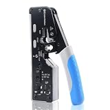 Cable Matters All-In-One Modular Ethernet Crimping Tool Cat 8
- All-In-One Cable Creator: Create professional-quality Ethernet cables with this Cat 8 Ethernet cable crimping tool. Use this shielded Cat6 crimp tool with bulk Ethernet cable and connectors to build custom-length patch cables for your network.
- Cut, Strip & Crimp in One Tool: This shielded RJ45 crimp tool pass through combines a wire cutter, wire stripper, and wire crimper for an all-in-one solution. The Cat6a shielded crimp tool makes it easy to create custom-length ethernet wire quickly and efficiently.
- Broad Ethernet Compatibility: This RJ45 pass through crimp tool works with Cat5, Cat6, Cat6A, Cat7, and Cat8 shielded Ethernet connectors. It is compatible with RJ11, RJ12, and RJ45 connectors and supports both pass-through connectors and standard RJ45 connectors. This RJ45 crimp tool features an adjustable switch to adjust the crimp type and a built-in crimping clip for shielded dovetail clips found on shielded cable.
- Pass-Through Simplicity: The Cat 8 crimping tool is optimized for pass-through connectors, simplifying wire termination and reducing errors. Just insert, pass through, and crimp with this shielded Cat6 crimp tool for reliable results every time.
- Rugged, Durable Design: This RJ45 crimp tool shielded is built with a durable metal frame for long-lasting performance. Ideal for IT professionals, network installers, and DIYers looking for a reliable Ethernet crimping tool for home or commercial networks.
Test the finished cable with a wire-map tester
Test before connecting the lead to a switch, router, wall jack, computer, or other powered equipment. A modular tester’s controls and display vary by model, so use its manual for the exact start button and indicator meanings. Fluke’s cable-testing material describes verification tools as devices that check whether all wires reach the proper termination points and not other conductors: Verification test tools perform basic continuity functions, they assure that all wires in a cabling link are connected to the proper termination points and not to any other conductors.
That is a wiring check, not a performance certification.
-
1. Isolate the cable
Disconnect both ends from network equipment. Testing a cable while it is connected can produce confusing indications and is unnecessary for a simple patch lead.
-
2. Connect the tester
Plug one end into the tester’s main unit and the other end into its remote unit. Make sure each modular plug is fully seated. A loose plug can look like an open conductor even when the cable itself is correctly wired.
-
3. Run the wire-map function
Start the tester’s wire-map or continuity test. Some units sequence through pins automatically; others require a test button. Read the model’s display or LED legend rather than assuming every tester uses the same animation or numbering.
What’s actually slowing this PC down?
Pick the symptom - the matching free tool is one click away.
Special offer. See more information about Outbyte and uninstall instructions. Please review EULA and Privacy policy. -
4. Confirm a straight-through map
For the cable made here, the expected map is 1-to-1, 2-to-2, 3-to-3, 4-to-4, 5-to-5, 6-to-6, 7-to-7, and 8-to-8. A pass normally indicates that the tester sees the intended one-to-one connections, subject to that tester’s capabilities.
Best Value
 Solsop Pass Through RJ45 Crimp Tool Kit All-in-One Ethernet Crimper
- Multi-Modular RJ45 Crimper - The Ethernet Crimper is ideal for stripping, cutting, crimping CAT5 CAT5e, CAT6,CAT6A,CAT7 cable and RJ11/RJ12 standard and Pass Through RJ45 connectors with dovetail clip
- Crimping Shield Cable Function - This Pass through rj45 crimp tool is suitable for both shielded and unshield modular plugs, especially for pass through modular plugs with metal dovetail clips
- Network Cable Tester - We upgraded cable tester, which is not only more durability, but also the test range can reach up to 300M, the Network Cable Tester for cables with RJ45/RJ11/RJ12 conectors(9V battery not included)
- Compact design - compact, non-slip comfort grip reduces hand fatigue - one-handed operation for easy storage, precision crimping dies and blades provide long-lasting tools for faster, more reliable cutting, stripping and crimping
- Kit included - Use's manual, RJ45 pass through crimp tool, 50PCS cat6 connector, 50PCS boots, network cable tester, mini wire stripper
-
5. Recheck a failure before using the cable
If the tester reports a fault, leave the cable disconnected from equipment, identify the indicated pins, and inspect or reterminate the affected end. Do not put a failed lead into service on the assumption that an attached device will compensate for it.
Understand what the tester result means
| Indication | Likely meaning | Action |
|---|---|---|
| 1-to-1 through 8-to-8 | The tester sees the expected straight-through mapping. | Use the cable for the intended installation, while remembering that this does not prove category performance or speed. |
| Open | A conductor or contact is not electrically connected end to end. Causes include a wire that did not reach the contact, a damaged conductor, or an incompletely seated plug. | Inspect the reported pin and the corresponding contact at both ends; cut off and reterminate if the contact is suspect. |
| Short | Two conductors are electrically joined where they should not be, often from a misplaced strand, damaged insulation, or a malformed crimp. | Discard the bad termination and make a fresh one after checking for stray copper or damaged insulation. |
| Crossed, reversed, or miswired | A conductor reaches a different pin than the one expected. A-to-B termination produces the characteristic crossover relationship; a single misplaced wire produces another mapping error. | Compare each end with the selected pinout and reterminate the end whose order is wrong. |
| Intermittent or changing result | A plug may be loose, a contact may be marginal, or the cable may be flexed at a damaged termination. | Reseat both plugs, test without moving the cable, then replace the suspect plug or cable if the result changes. |
| Continuity passes but network performance is poor | The wiring may be one-to-one while pair twisting, insertion loss, crosstalk, length, or another transmission property is outside the required limit. A split pair can evade a simplistic continuity-only test because each conductor still has a path. | Use a tester that can identify pair integrity and perform the appropriate qualification or certification test; inspect pair order and excessive untwisting. |
Basic testers do not all display “open,” “short,” “cross,” or split-pair conditions in the same way. Consult the legend for the exact model. The distinction between continuity and pair integrity is explained in Fluke Networks’ wire-map article and its split-pair guidance.
Wire-map verification versus qualification and certification
Select the test level that matches the decision you need to make. A one-off home patch cable usually needs a wiring check; an installed cabling link that must meet a category or project specification needs broader measurements and the correct test limits.
PC Slower Than It Used to Be?
A free scan shows the junk files, broken settings and background clutter dragging Windows down - then fixes them in one click.Free scan · Windows 10 & 11Crashes, No Sound, or Screen Glitches?
Random freezes, missing sound and display glitches usually trace back to one bad driver. Find and replace yours safely.Free scan · under a minute| Test level | What it establishes | What it does not establish | Typical use |
|---|---|---|---|
| Verification (basic wire map) | Continuity and the apparent mapping of conductors to termination pins; it can reveal many opens, shorts, and miswires. | It does not certify insertion loss, return loss, crosstalk, length limits, category compliance, supported speed, or PoE suitability. | Checking a newly crimped patch lead for termination mistakes. |
| Qualification | Broader performance testing against the capabilities and limits supported by the qualification instrument. | It is not automatically a formal certification report for every cabling standard or installation class. | Determining whether an existing link is likely to support a specified network application. |
| Certification | Measurements made with an appropriate certification tester against a selected cabling standard and permanent-link or channel limits, producing a compliance result. | It still depends on correct test setup, adapters, limits, and the standard selected. | Acceptance of structured cabling where documented compliance is required. |
Fluke Networks’ testing overview separates basic verification from qualification and certification. Do not describe a glowing LED on an inexpensive wire mapper as proof that a cable is “Cat 6,” “gigabit,” “10-gigabit,” or Power over Ethernet ready.
Troubleshoot the most common mistakes
The colors look right, but the tester shows an open
- Check that the affected conductor reaches the front of the plug rather than stopping behind a contact.
- Confirm that the jacket is supported and the plug was fully crimped.
- Inspect for a nick made while stripping; cut back and reterminate if copper or insulation is damaged.
- Swap in a known-good tester battery or check the tester with a short known-good lead before condemning the cable.
The tester shows a crossed or reversed conductor
- Hold each plug in the orientation used by its pin diagram and read the order from pin 1 to pin 8.
- Check that you did not mirror the sequence when turning the cable around for the second end.
- Verify that both ends use the same scheme; an A-to-B pair is a crossover, not a straight-through cable.
Every pin has continuity, but the link is slow or unreliable
- Check for a split pair or a pair that was rearranged despite one-to-one continuity.
- Look for excessive untwisting near either plug, crushed cable, sharp bends, or a plug not rated for the cable.
- Test the installed link with equipment appropriate to the required category and application instead of relying on the basic wire map.
The plug will not fit the cable conductors
- Stop rather than forcing the conductors into the channels.
- Verify stranded versus solid compatibility, conductor gauge, insulation diameter, and the plug’s category specification.
- Obtain a matching plug and crimper; changing only the crimper rarely fixes an incompatible connector.
The network works only when the cable is held a certain way
- Flex-sensitive behavior usually indicates a marginal contact, damaged conductor, or inadequate strain relief.
- Replace the affected termination and retest while gently moving the cable near each plug.
- If the fault follows the cable after both ends are remade, replace the cable rather than continuing to reuse damaged material.
Practical checks before putting the cable into service
- Both ends use the same documented scheme for a straight-through patch cable.
- The plug model accepts the cable’s conductor construction and dimensions.
- The jacket is captured by the connector’s strain relief, with only the required short length untwisted.
- All eight conductors are fully inserted and visible at the intended contacts before crimping.
- The crimper matches the plug design and was closed as specified by its instructions.
- The tester is connected with the cable isolated from network equipment.
- The wire map reads pin 1 through pin 8 one-to-one.
- Any claim about category, speed, PoE, or installed-link compliance is backed by the appropriate qualification or certification test, not just continuity.
Once these checks pass, connect the lead to the network. If the link still fails, test the wall jack, patch-panel ports, transceiver, and switch or router separately; a correct patch-cable wire map cannot rule out faults elsewhere in the channel.
Quick Recap
Product prices and availability are accurate as of the date/time indicated and are subject to change. Any price and availability information displayed on Amazon at the time of purchase will apply.

