
Quick wins for a faster PC:
Scan for outdated or missing drivers - takes under a minuteDriver Scan →Clear out junk files and repair common Windows errorsFree Scan →iTechGuides is reader-supported. When you buy through links on our site, we may earn an affiliate commission. As an Amazon Associate I earn from qualifying purchases. Learn more
Install two DDR4 desktop DIMMs in the motherboard slots shown by its manual—often A2 and B2—seat each module until both retention latches lock, then verify the total memory in BIOS/UEFI before enabling XMP. Correct slot population, matched compatible modules, and a one-stick recovery test prevent most no-POST and missing-memory problems.
What you need to check before installing DDR4
DDR4 installation is physically simple, but the correct slots and supported memory settings vary by motherboard and processor. Gather the exact motherboard manual, the processor specifications, and the memory kit’s part number before opening the case.
- Motherboard manual: Find the diagram labeled DIMM, DRAM, or memory population. It identifies the slots as A1, A2, B1, and B2 and shows the approved one- and two-module arrangements.
- Processor and motherboard compatibility: Confirm that the board and CPU support DDR4 and the kit’s capacity and rated settings. Memory support is platform-specific; there is no single DDR4 speed or capacity that applies to every system.
- A matched kit: For a first build, use modules sold as a kit with matching part numbers. Matching type and density helps dual-channel operation and stability.
- Basic hardware: Shut the computer down, switch off the power supply, unplug the AC cable, and work on a non-carpeted surface. Touch the metal chassis before handling a module, and hold DIMMs by their edges.
Do not rely on a slot layout remembered from another board. Two-module A2/B2 placement is common, but the manual’s A1/A2/B1/B2 diagram is authoritative.
Which slots should you use for two DDR4 sticks?
Use the pair specified for two modules in the motherboard manual. Many MSI boards designate DIMMA2 and DIMMB2, which are typically the second slot away from the CPU socket in each channel. Other boards can use a different arrangement, so confirm the labels printed beside the sockets and the manual’s population table.
#1 Best Overall

- Disclaimer: Maximum Speed requires overclocking/PC BIOS adjustments. Maximum speed and performance depend on system components, including motherboard and CPU
- Hand-sorted memory chips ensure high performance with generous overclocking headroom
- VENGEANCE LPX is optimized for wide compatibility with the latest Intel and AMD DDR4 motherboards
- A low-profile height of just 34mm ensures that VENGEANCE LPX even fits in most small-form-factor builds
- A solid aluminum heatspreader efficiently dissipates heat from each module so that they consistently run at high clock speeds
| Installation goal | What to do | Why it matters |
|---|---|---|
| One DIMM for initial testing | Use the single-module slot named in the manual, commonly A2 but not universal. | The board’s memory-training routine expects a particular slot for a lone module. |
| Two matched DIMMs | Use the manual’s two-module pair, often A2 and B2. | This normally places one module in each memory channel for dual-channel operation. |
| Four DIMMs | Populate all four only if the board and CPU support the combination. | Four modules can change the supported speed or stability requirements. |
Never infer the correct pair solely from physical spacing. A slot can look usable while being electrically different from the one required for a two-stick configuration.
How to install the modules, step by step
1. Power down and expose the DIMM sockets
Turn the system off, switch the power supply to its off position, unplug the AC lead, and press the case power button briefly to discharge residual power. Remove the side panel. If a large CPU cooler or graphics card blocks access, follow the case or component instructions before forcing a DIMM into place.
2. Open the retention clips
Move the locking tabs at the ends of the selected DIMM sockets to the open position. Some boards have a movable latch at both ends; others have one fixed end and one movable end. Do not remove a latch or lever it beyond its normal travel.
PC Slower Than It Used to Be?
A free scan shows the junk files, broken settings and background clutter dragging Windows down - then fixes them in one click.Free scan · Windows 10 & 11Crashes, No Sound, or Screen Glitches?
Random freezes, missing sound and display glitches usually trace back to one bad driver. Find and replace yours safely.Free scan · under a minute3. Align the notch
Look at the keyed notch along the gold contacts of the DDR4 module and compare it with the raised key inside the socket. The notch is intentionally off-center. Rotate the DIMM if the key does not line up; never try to slide a misaligned module into the slot.
Rank #2

- Actual memory speed may vary depending on the system, CPU, motherboard, BIOS settings, and supported memory configuration. DDR4 3200MHz modules may operate at lower speeds such as 2933MHz or 2666MHz when supported by the host system. Please check your device specifications and compatibility before purchase.
- Adherence to JEDEC and compliance to RoHS with respect to environmental protection regulation, production and manufacturing
- All new generation product of DRAM module. Strict test and verification procedures are performed for products
- Lifetime warranty and Free technical support
- ※ Refer to the latest version on the official website. In case of discrepancies, the official website prevails.
4. Press straight down
With the notch aligned, place the module evenly over the socket and press down firmly on both ends at the same time. The module should descend straight into the contacts. Continue until the retention clips swing up and lock into the notches at each end. ASUS and MSI both describe notch alignment followed by pressing until the latches lock as the seating sequence.
5. Install the second module
Fit the second matched DIMM in the other slot of the recommended pair. Apply the same alignment and even pressure. Compare both modules visually: their top edges should be at the same height, and every latch should be fully engaged.
6. Reassemble enough to test
Reconnect the 24-pin motherboard cable, CPU power cable, graphics power leads, and any fan cables that were disturbed. You can leave the side panel off for the first test, but keep fingers and loose cables away from fans. Connect a monitor to the output driven by your graphics card or processor, as appropriate.
Free tools Windows power users keep installed
One-click scans. No signup required.
First boot: verify memory before changing settings
Power on and enter BIOS/UEFI, commonly by pressing Delete repeatedly as the system starts. The exact key may be shown on the startup screen or in the manual.
Rank #3

- Disclaimer: Maximum Speed requires overclocking/PC BIOS adjustments. Maximum speed and performance depend on system components, including motherboard and CPU
- Hand-sorted memory chips ensure high performance with generous overclocking headroom
- VENGEANCE LPX is optimized for wide compatibility with the latest Intel and AMD DDR4 motherboards
- A low-profile height of just 34mm ensures that VENGEANCE LPX even fits in most small-form-factor builds
- A solid aluminum heatspreader efficiently dissipates heat from each module so that they consistently run at high clock speeds
- Open the page labeled Memory, DRAM, System Information, or a similar status screen.
- Check that the expected number of modules is listed.
- Check that the total capacity equals the sum of the installed DIMMs.
- Confirm that each channel or slot is identified, if the firmware provides that detail.
- Save nothing yet if a module is missing. Shut the system down and reseat the unrecognized DIMM.
Memory training can make the first start take longer than a normal boot. Do not interrupt it immediately, but if the system repeatedly powers on without displaying BIOS, use the recovery procedure below rather than repeatedly cycling the power.
Why matched, compatible modules matter
Use a kit whose modules were validated together whenever possible. Intel’s installation and troubleshooting guidance warns that mixing unrelated DIMMs can lower the operating speed or prevent the system from booting. Even modules with the same advertised speed can use different chips, ranks, or timing tables.
When comparing a kit, record these values and check them against the motherboard and CPU documentation:
| Selection factor | What to verify |
|---|---|
| Compatibility | Motherboard and processor support for DDR4, the total capacity, and the planned number of modules. |
| QVL listing | Whether the exact kit part number appears on the board’s qualified-vendor list. A QVL is useful evidence of validation, not a guarantee that every other kit will fail. |
| Total capacity | The combined capacity needed by the operating system and applications, within the platform’s documented limit. |
| Number of sticks | Two matched modules are usually easier to run than four; the board manual and CPU specifications determine the supported combinations. |
| Rated speed and voltage | The values printed on the kit and the settings the platform supports. Do not assume the advertised profile is the default operating setting. |
| Part-number matching | Use identical part numbers for a pair rather than combining separate purchases. |
| XMP profile | Check that the desired profile is intended for the platform and can be disabled if the system is unstable. |
Should you enable XMP?
Leave XMP off until the new system reaches BIOS reliably with default settings and reports the correct capacity. Intel describes XMP as an overclocking feature for compatible DDR4 and DDR5 modules; it applies a stored profile containing higher performance settings than the platform’s baseline.
Rank #4

- Capacity – 32GB RAM KIT (2 x 16GB Modules) Speed up to 2666MHz Non-ECC Unbuffered 288-Pin 1.2V UDIMM.
- Specs – Black PCB Color and Dual Rank (2Rx8).
- Compatibility – Designed for selected DDR4 Desktop PCs and workstations that support 288-Pin UDIMM memory. NOT compatible with Laptop SODIMM slots.
- Installation – Plug-and-Play Upgrade, Quick and Easy to Install, no expertise required (please refer to your system's manual for guidelines).
- Warranty – All Timetec products are high-quality and rigorously tested to meet stringent standards. Backed by Timetec Limited Lifetime Warranty and professional technical support based in the United States.
After the default configuration is stable:
- Enter BIOS/UEFI.
- Find the memory-overclocking or XMP control. The label and location depend on the board.
- Select the desired XMP profile, if more than one is offered.
- Save and reboot.
- Return to BIOS and confirm that the system still recognizes every module.
If the machine fails to POST, loops through restarts, or becomes unreliable after enabling XMP, reset BIOS to defaults or disable XMP and retest. Treat the profile as a later tuning step, not part of the physical installation.
What to do when the new PC will not POST or shows no display
A no-POST condition means the system has not reached the stage where it can show normal firmware or operating-system output. Follow the checks in order, changing one variable at a time.
1. Reseat every module
Switch the power supply off and unplug the system. Remove each DIMM and reinstall it with the notch aligned. Press evenly until the retaining clips lock. A module that is partly inserted can look level while one or both latches remain open.
Do these 3 things before closing this tab:
1Repair Windows errors before they cause bigger problems2Scan for outdated or missing drivers - takes under a minute3Clear out junk files and repair common Windows errors2. Test one compatible stick
Remove all but one known-compatible DIMM and place it in the motherboard’s recommended single-DIMM slot. MSI specifically recommends one-stick testing when multiple modules fail. If the computer reaches BIOS, shut down and test the other module separately.
Best Value
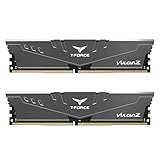
- Simple design to perfectly protect the cooling module with high thermal conductive adhesive
- Supports Intel & AMD motherboards
- Selected high-quality IC
- Supports XMP2.0
- Energy saving with ultra-low working voltage
3. Test modules and slots methodically
Use the same known-good stick in the recommended slot, then in each other slot if necessary. Repeat with the second stick. Record which combinations reach BIOS. This separates a bad or incompatible DIMM from a slot, channel, or configuration problem.
4. Load BIOS defaults
Clear any unsuccessful memory settings by using the firmware’s Load Optimized Defaults or equivalent command. If you cannot reach the menu, use the motherboard’s documented CMOS-reset procedure with power removed. Do not enable XMP while diagnosing a baseline boot failure.
5. Check firmware and platform support
Intel lists BIOS updates and verification of processor and memory compatibility among the primary troubleshooting steps. Compare the board’s installed BIOS version with the CPU support list and the memory requirements in the manual. Update BIOS only by following the board manufacturer’s exact procedure and power requirements.
6. Read diagnostic indicators
Watch the motherboard’s DRAM or EZ Debug LED, or listen for its documented beep indication. MSI notes that these indicators can identify the stage at which startup stops. A DRAM indication points you back to seating, slot population, compatibility, and default settings before you investigate unrelated components.
7. Add the second stick only after the first works
Once one-stick configuration consistently reaches BIOS, power down and install the second module in the prescribed pair. If the failure returns, repeat the individual-stick and individual-slot tests and consult the board’s QVL and manual. Do not assume the second module is defective until it has been tested alone in a known-good slot.
Independent reader supportYour contribution helps us test, update, and keep practical guides available for everyone.Symptoms and likely checks
| Symptom | First checks | Next action |
|---|---|---|
| System powers on but no display appears | Reseat modules, verify the single-DIMM slot, and remove all but one stick. | Load BIOS defaults and test each module and slot separately. |
| BIOS shows only one of two modules | Shut down and reseat the missing module; confirm the pair matches the manual’s slot diagram. | Test that module alone, then inspect the alternate slot and QVL. |
| Boot failure begins after XMP is enabled | Disable XMP or reset BIOS to defaults. | Run at default settings first; only then retry the profile. |
| System boots but memory runs below the kit’s rating | Check whether the rated value requires XMP and whether the CPU/board supports it. | Use the documented profile only after baseline stability is established. |
| Four modules are unstable while two work | Confirm four-DIMM support and the platform’s guidance for that load. | Use the supported configuration or a matched kit validated for the board. |
A practical installation and verification checklist
- Read the exact motherboard manual and identify the approved one- and two-DIMM slots.
- Confirm DDR4 compatibility with the motherboard and processor.
- Use a matched kit and avoid mixing unrelated part numbers.
- Turn off and unplug the system before touching memory.
- Open the socket latches and align the DDR4 notch with the socket key.
- Press evenly until every retention clip locks.
- Start with default firmware settings and enter BIOS/UEFI.
- Verify module count and total capacity.
- If BIOS misses a module, reseat it before changing any performance setting.
- For no-POST problems, use one stick in the recommended slot, then test sticks and slots separately.
- Use BIOS defaults, compatibility checks, firmware guidance, and debug LEDs in that order.
- Enable XMP only after reliable baseline boots, and disable it again if instability appears.
When the installation is complete
The installation is successful when the modules are fully latched, BIOS/UEFI reports the expected count and capacity, and the system can repeatedly start at default settings. At that point, XMP is an optional performance setting rather than a requirement for recognizing the memory. Keeping the manual, kit part number, tested slot arrangement, and any stable BIOS profile with the build record makes future upgrades and troubleshooting much easier.
Quick Recap
Product prices and availability are accurate as of the date/time indicated and are subject to change. Any price and availability information displayed on Amazon at the time of purchase will apply.
The Tool Desk
Outbyte PC Repair FREEClear out junk files and repair common Windows errorsFree Scan →Outbyte Driver Updater FREEScan for outdated or missing drivers - takes under a minuteDriver Scan →
