
Windows Errors? Fix Them Before They Spread
Repair common Windows errors and clear accumulated junk for a smoother, more stable PC - no reinstall needed.Free scan · no reinstallOutdated Drivers Are Slowing You Down
One free scan finds every outdated or missing driver and matches the right update for your exact hardware.Free scan · exact hardware matchiTechGuides is reader-supported. When you buy through links on our site, we may earn an affiliate commission. As an Amazon Associate I earn from qualifying purchases. Learn more
A 3D-printed PC accessory fits reliably when you design it around the installed computer, not a generic case drawing. Measure the real mounting points, cable paths, openings and service clearances; make those dimensions adjustable in CAD; print a small interface test; revise it; then validate the installed part for strength, heat, airflow and maintenance access.
This workflow works for cable guides, clips, brackets, spacers and dust-filter frames. It also prevents the most expensive mistakes: a part that almost fits, blocks a fan, traps a cable, cracks along its layers or cannot be removed when the PC needs servicing.
The fit-first workflow
Use this sequence for every custom accessory, regardless of whether the final print is tiny or spans a panel.
Quick wins for a faster PC:
Fix the driver behind crashes, sound loss and screen glitchesFind Drivers →Repair Windows errors before they cause bigger problemsFix Now →- Define the job and its boundaries. State what the part must hold, guide or protect, what it must not touch, and how it will be attached.
- Measure the powered-off build. Capture actual datums, holes, edges, openings, cable bends and the space needed to install, remove and service the part.
- Model adjustable geometry. Keep attachment dimensions, wall thickness, clearances and openings as named parameters rather than hard-coded sketches.
- Make it printable and durable. Choose an orientation that supports the load, limits supports and avoids long, thin sections that can warp.
- Print an interface coupon. Test only the critical hole, clip, slot or mating surface with the same printer, material, orientation and slicer settings intended for the final part.
- Install and validate. Check fit, retention, cable movement, fan clearance, connector access, temperatures and service access before considering the design finished.
Each loop should produce an observable change: a measured dimension, a fit result or an installation check. If a change cannot be tied to evidence from the physical build, it is guesswork.
#1 Best Overall
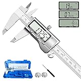
- 【STAINLESS STEEL MATERIAL】The vernier caliper is made of high-strength stainless steel and is waterproof and dirt-proof. The service life of this stainless steel digital caliper is longer than that of calipers with plastic or carbon fiber parts.
- 【ACCURATE MEASUREMENT AND ZERO SETTING】This digital caliper glides smoothly. Measuring range: 0 -6" / 0-150mm; Accuracy: ± 0.001"/ 0.02mm; Resolution: 0. 0005"/0. 01mm. At the same time, the smart design allows you to easily reset to zero by pressing a button and start a new measurement at any point on the scale, which is very suitable for differential measurement.
- 【4 MEASUREMENT MODES】The digital caliper has 4 measurement modes, which can be used to measure inside and outside diameter, depth, and step with two sets of jaws and a probe. Multiple measurement modes can bring more usage scenarios to people, and the measurement process is also very convenient.
- 【UNIT CONVERSION & LARGER LCD SCREEN】These Digital Calipers have a one-key button to quickly switch from inches (inch), fractions (F), millimeters (mm). The 6" digital caliper has a large, easy-to-read LCD DISPLAY which is easy to use and read even under strong sunlight. It will automatically turn off after 5 minutes of non-use to save power.
- 【Wide Applications】 Compared to the ordinary rulers, this stainless steel caliper can measure not only length but also caliber and depth, allows you to measure circular and cylindrical objects, more functions and better performance will satisfy you. It has always been used by professionals and hobbyists alike, jewelers, hobbyists, woodworkers, machinists, DIY, automotive mechanics, and more.
1. Define a useful job and a safety boundary
Start with one sentence such as “route the front-panel cable along this edge without covering the intake” or “support this sensor cable at the existing screw location.” A narrow job gives you a clear acceptance test. A vague goal such as “tidy the inside” tends to produce a part that interferes with something else.
Write what the part may and may not touch
- A cable guide may contact insulation, a case flange and its own fastener, but it must not pinch the cable or abrade a connector latch.
- A bracket should use an existing mounting point where possible. It must not push a board, radiator or drive into a neighboring clearance envelope.
- A spacer must remain captive under the expected load and must not become loose hardware that can fall into a fan.
- A dust-filter frame can cover an opening, but it must leave the filter media removable and must not seal against a surface that needs cooling airflow unless that is the intended design.
Assume that a detached print is a hazard. Design retention so a broken clip or dropped spacer cannot reach a rotating fan or exposed electrical contacts. Avoid placing an accessory where a tool, screw or cable tie could short electronics during installation.
Set acceptance tests before modeling
Record a few pass/fail checks: the cable slides without damage, the bracket remains fixed when the cable is pulled, the panel still closes, the filter can be removed, and every connector can be unplugged. Include a removal test. A part that fits only while the PC is disassembled is not a successful accessory.
What’s actually slowing this PC down?
Pick the symptom - the matching free tool is one click away.
2. Measure the actual installed environment
Turn the computer off, unplug it and allow hot components to cool. Remove a panel only when you can do so safely. Measure the assembled system rather than relying on a case model’s nominal dimensions: case revisions, motherboard layouts, graphics cards, radiators, drive cages and cable routes vary from one build to another.
Use datums and a measurement record
Choose stable reference surfaces, called datums, such as the inside face of a panel or the centerline of an existing screw hole. Every important dimension should be measured from a named datum. This makes a later revision intelligible instead of leaving you with unrelated numbers.
Rank #2

- [INCH/MM Conversion]: One button can quickly convert two measuring unit (INCH/MM). Measuring Range:0 - 150mm (6") / Resolution: 0.01mm (0.0005")/Accuracy: ±0.02mm (0.001")
- [Stainless Steel Material]: The vernier caliper is made of high-strength stainless steel, which is waterproof, stain-proof and oil-proof. The ergonomic design brings you a comfortable feeling.
- [Large and Clear Display Screen]: Large LCD display gives you a clear reading. The thumb rolling and locking screw provide easy sliding, accurate positioning, and fine adjustment.
- [Multifunctional Use]: The digital micrometer can easily and accurately measure internal, external, height and depth dimensions.
- [Automatically shut off]: When you have no action on the dial caliper, it can automatically shut off after 4 minutes.
Digital calipers are useful for hole diameters, slot widths, edge offsets and print checks. For large spans, use a ruler or tape and note where the measurement starts and ends. Measure twice, especially when a dimension controls a snap fit or a screw pattern.
| Measure | Why it matters | How to record it |
|---|---|---|
| Mounting holes, slots and edge offsets | Determines attachment geometry and alignment. | Hole center-to-center distances, diameter or slot length, and datum faces. |
| Nearby component envelope | Prevents contact with boards, heatsinks, radiators, drives and panels. | Maximum occupied width, height and depth, including plugs and cable bends. |
| Opening and airflow area | Shows whether a guide, frame or bracket intrudes into ventilation. | Opening dimensions plus the region that must remain unobstructed. |
| Installation and removal path | A part may fit in its final position but be impossible to insert or remove. | Direction of travel, tool access and the extra space needed to pivot or slide it. |
| Cable route and bend | Prevents sharp bends, pinching and connector strain. | Cable outside diameter, bend direction, latch location and slack required. |
Measure service access, not only the resting position
Open the side panel, unplug the relevant connector and remove the component that a future upgrade would affect. Note the space needed for fingers, a screwdriver and the component’s extraction path. A bracket that blocks one screw or a cable guide that prevents a connector from releasing creates a maintenance problem even if the PC operates normally.
Nominal standards or dimensions from a product page can help you orient a design, but they do not replace checking the particular build. The installed combination is the geometry your print must fit.
3. Model dimensions that can be revised
Use a parametric or otherwise constraint-driven CAD workflow. Name the dimensions that are likely to change: mount_spacing, hole_diameter, wall, cable_opening, edge_clearance and service_gap. Keep these values in one place so a fit-test result leads to a controlled revision.
Build around the attachment first
Model the interface that locates the part before adding cosmetic features. For a screw-mounted bracket, start with hole centers and the contact face. For a clip, start with the thickness of the edge it grips and the insertion direction. For a spacer, start with the two surfaces it separates. This order keeps the functional geometry easy to inspect.
Rank #3

- Best Cost-effectiveness: We've crafted this plastic digital caliper with a singular focus – delivering unmatched value at an unbeatable price. While others chase high-precision innovations, we prioritize essential features that truly matter.
- 4 Measurement Modes and Precision: Outside diameter, inside diameter, depth, and step measurements. Measurement range: 0-6 inches / 0-150 mm, accuracy: ±0.2 mm / 0.01 inches. Whether it's for home projects, DIY, or 3D print, having this caliper will elevate you to be a measurement star.
- Low Energy Consumption Design with Smart Auto-Off Function: With just a single battery, our caliper can support 8+ months of measurements. It can automatically turns on when you slide it, and turns off within 5 mins when not in use, effectively conserving battery power.
- Tough Plastic Case Packaging and Secure Measurements: The plastic case packaging effectively protects the caliper from external impacts and friction, ensuring that it stays in optimal condition at all times. Moreover, our digital caliper is made of extra strong carbon fiber composites that are not easy to damage the measured object during use.
- What You Get: Digital Caliper *1, Tough Plastic Case *1, and LR44 button batteries *3(with one pre-installed). Additionally, we offer a lifetime warranty and friendly customer service to ensure your complete satisfaction.
Add lead-ins and forgiving transitions
Chamfers, radiused edges and tapered entrances help a part slide into place and reduce stress concentrations. They are especially useful on a cable opening and on a clip that is installed repeatedly. Do not rely on a tight snap fit until a coupon has demonstrated that your printer and material produce the required spring behavior.
Free tools Windows power users keep installed
One-click scans. No signup required.
Keep the model simple enough to print repeatedly
A simple U-shaped guide or flat bracket is easier to orient, support and revise than a sculpted enclosure. Separate cosmetic ribs from load-bearing walls. If a feature does not serve the stated job, leave it out of the first revision; every extra feature is another possible interference or failure point.
Choose an attachment method deliberately
| Method | Best use | Design questions |
|---|---|---|
| Existing screw or standoff | Brackets and fixed guides that need positive retention. | Can the original fastener still be inserted and removed? Is the printed wall strong around the hole? |
| Edge clip | Light cable management or removable covers. | What edge thickness does it grip? Will repeated flexing load the print across weak layers? |
| Slide-in rail or dovetail | Parts that need tool-free removal, such as a filter frame. | Is there a clear insertion path and a stop that prevents the part falling inward? |
| Adhesive or tie point | Low-load routing where drilling or hardware is undesirable. | Will heat, dust or cleaning loosen it, and can the cable be replaced without destroying the mount? |
4. Select a material for the printer and the location
Material choice is a joint decision about the printer, the part’s load and the environment around it. A cable guide in a cool, low-load area has different requirements from a bracket near a warm radiator or a part that must flex during every service operation.
Use polycarbonate only when its advantages justify its difficulty
Prusa Research describes polycarbonate (PC) as suitable for technical parts that need high mechanical and temperature resistance, while also noting that PC is challenging to print. It can be a sensible choice for a demanding location when your printer, enclosure and process are capable of producing it consistently. It is not automatically the right choice for every case accessory.
Match the material to the real conditions
- Confirm that your printer can process the chosen filament reliably; a material specification alone does not guarantee a successful print.
- Consider heat exposure, sustained load, flexing, vibration, dust and contact with cleaning products at the exact location.
- Do not describe any filament as universally safe near all PC components. Check the local temperature and keep the accessory away from hot surfaces unless the material and design have been validated there.
- Use the same material for the coupon and final part. A gap that works in one filament may bind or become loose in another.
5. Design for layer direction, strength and warping
Fused-deposition prints are not equally strong in every direction. Place a clip, tab or hook so its working load does not depend on a weak layer-to-layer interface. If the feature must flex, test that flex in the actual print orientation rather than assuming the CAD shape describes its strength.
Do these 3 things before closing this tab:
1Scan for outdated or missing drivers - takes under a minute2Repair Windows errors before they cause bigger problems3Fix the driver behind crashes, sound loss and screen glitchesRank #4
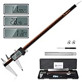
- 【Stainless steel material】Digital calipers are made of high quality stainless steel, waterproof and rustproof, and the sturdy frame reduces the wear and tear of vernier calipers, allowing a longer service life
- 【Accurate measuring range】 0-12 inches/300mm; Display: 14mm x 40mm oversized LCD; Accuracy: ±0.04mm/0.0015 inches; Resolution: 0.01 mm/0.0005 inches. The knurled thumb roller ensures smooth gliding in use; the locking screw enables accurate positioning. These two designs ensure smooth operation during measurement and prevent slippage or jams from occurring
- 【4 measurement modes】The digital caliper comes with two pairs of jaws and a probe to easily measure depth, step length, outside diameter and inside diameter. Four measurement methods meet most of your measurement needs
- 【3 unit conversions】 With the push of a button, you can quickly switch between the 3 units of the digital caliper: inches, millimeters and fraction; plus the large LCD screen makes it easy to read. You can reset it to zero with the zero button, plus the digital vernier caliper will automatically turn off after 5 minutes of non-use to save power
- 【Wide application】HARDELL digital caliper comes with 1*ruler, 1*screwdriver, 2*batteries. The case is resistant to pressure, shock and drop for easy storage and carrying. 12 inch caliper micrometer has been used by professionals and amateurs, it is the best choice for mechanics, woodworkers, jewelers, craftsmen, DIY enthusiasts, auto mechanics, etc
Reduce unsupported and slender geometry
Unnecessary overhangs increase support cleanup and can change a critical dimension. Long, thin sections can warp; HP’s Multi Jet Fusion guidance also warns about warping in long, thin geometry, which is a reminder that slender shapes need process-specific attention even when the manufacturing method differs. Add ribs, shorten unsupported spans or change the orientation when those changes preserve the job’s clearance.
Protect critical interfaces
Keep screw holes, slide rails and clip mouths away from large support scars. If a support must touch an interface, make the interface a separate coupon or leave machining and cleanup allowance that you can measure. A smooth cosmetic surface is less important than a repeatable mounting surface.
6. Establish tolerances with a fit coupon
There is no universal “3D-print clearance.” Dimensional fit depends on part size, orientation, geometry, printer calibration, slicing settings and material. Print a small section containing the actual interface before committing to a full accessory.
Use the same process as the final part
- Copy the critical hole, peg, slot, clip mouth or mating edge into a small test model.
- Use the intended printer, nozzle, material, layer strategy, orientation and relevant slicer settings.
- Measure the printed feature with calipers and compare it with the CAD value.
- Test the physical mating action: slide, rotate, clip, screw or remove it as the final part will.
- Change the parameter that explains the observed error, then print the coupon again.
| Published figure | What it describes | How to use it |
|---|---|---|
| 0.3 mm initial gap | Prusa Research’s guidance for movable parts on an Original Prusa. | Use only as an initial example for that printer context; it is not a universal PC-accessory tolerance. |
| 0.4 mm starting interface gap | HP guidance for connecting parts in Multi Jet Fusion (MJF), with separate considerations for moving assemblies. | Treat it as MJF-specific evidence that process changes clearance; do not copy it as a hobby FDM recipe. |
| 0.15% standard accuracy, lower limit ±0.2 mm | Materialise guidance for its FDM PC-ISO process. | Keep the figure attached to that specified process and material, not to every FDM printer or filament. |
The practical lesson from these different figures is to measure your own coupon. A larger nominal gap is not automatically safer: it may create rattle, allow a clip to disengage or shift a component into another clearance envelope.
7. Slice and print the final accessory
Once the coupon fits, orient the full model so the important load paths and interfaces remain reliable. Use supports only where they protect a necessary feature. Mark the version, material and orientation in the file name or project notes so a replacement can be reproduced.
Best Value

- Solid stainless steel build – This digital caliper 6 inch resists rust, wear, and corrosion, outlasting plastic models. The sturdy metal body handles daily workshop use without bending. The shockproof case protects your measuring tool from drops and impacts, keeping it safe and ready for each job
- Reliable accuracy with smooth glide – This digital vernier caliper measures 0‑6″ / 0‑150mm with ±0.02mm / 0.001″ accuracy and 0.01mm resolution. The thumb roller glides without sticking, and the locking screw holds your reading steady. From checking 3D print filament and woodworking joints to measuring jewelry and small parts for repairs, you can trust the results
- Four measurement modes in one – Use two jaw pairs and a depth probe for ID, OD, depth, and step measurements. No need to switch digital caliper measuring tool – this versatile dial caliper covers tubing, bores, recesses, and shoulders. Press the zero button anywhere to reset for quick comparative checks. Close and re‑zero before each use to ensure consistent readings
- Metric & Imperial conversion with large LCD – This electronic vernier caliper lets you switch between millimeters and inches with one click. The oversized LCD screen displays crisp, bold numbers that are easy to read at a glance. The wide viewing angle means you can read it clearly without tilting the caliper. Auto‑off powers down after 5 minutes of non‑use to save battery
- Complete kit – ready out of the box – Your package includes the digital micrometer, a sturdy case, two batteries (one spare), a mini screwdriver, and a stainless steel ruler. No extra trips to the store – just open and start working. A practical choice for DIYers, hobbyists, and makers who need reliable measurements at home or in the workshop
Inspect the first print before removing it from the build plate
- Check for corner lift, layer separation, under-extrusion, blocked holes and distorted thin walls.
- Measure the critical dimensions while the part is still easy to reference against the CAD model.
- Remove support material carefully; a damaged clip mouth or rail can invalidate an otherwise good print.
- Do not force a part into the case to “see if it settles.” Reprint or revise when the interface is visibly wrong.
8. Install and validate the part in the case
Install the accessory with the PC powered off. Follow the same insertion and removal path you measured. Confirm that fasteners seat fully, clips are not overstressed and cables retain their natural bend rather than being pulled toward the mount.
Check airflow and moving hardware
Leave fan inlets and outlets, fan blades, vents and radiator paths unobstructed. Do not rely on a made-up universal distance from a printed part to a fan or heatsink; the available evidence does not establish one safe clearance for all cases and accessories. If the part is near airflow-critical hardware, compare operation with and without it using the system’s own temperature monitoring and the component maker’s guidance. Do not claim a cooling improvement unless you have actually measured one.
Check heat and contact hazards
Inspect for contact with hot surfaces, sharp sheet-metal edges, exposed contacts and moving mechanisms. A printed part should not rub a fan, press on a board, trap dust against a connector or create a path for a loose fragment to enter the chassis interior.
The Tool Desk
Outbyte PC Repair FREEClear out junk files and repair common Windows errorsFree Scan →Outbyte Driver Updater FREEFix the driver behind crashes, sound loss and screen glitchesFind Drivers →Perform a service rehearsal
Open the panel, unplug the routed cable and remove the accessory as you would during maintenance. If the part blocks a connector latch, screw head or component extraction path, revise it before regular use. Recheck the installation after the first period of operation and after moving the PC, because vibration or cable tension can reveal a retention problem.
Worked design patterns
Cable guide
- Measure the cable’s outside diameter, connector dimensions, bend direction and the edge or hole where the guide will attach.
- Define a smooth channel with a lead-in and an opening large enough for insertion without forcing the connector.
- Use an existing screw, tie point or case edge for retention; avoid a guide that depends on adhesive alone in a warm or dusty location.
- Print a short section containing the channel and attachment feature. Test cable insertion, sliding and removal.
- Install the full guide and verify that no cable is pinched when the panel closes and that the guide cannot fall toward a fan.
Bracket
- Measure hole centers from stable datums and record the fastener head, washer and tool access.
- Model the mounting face first, then add a gusset in an orientation that carries the expected load along the stronger layer direction.
- Leave the original component’s clearance and an accessible path for the screwdriver.
- Coupon-test one hole and the bracket-to-case interface before printing the complete support.
- With the bracket installed, apply the expected hand load gently and inspect for cracking, layer separation or movement.
Spacer
- Measure both contact surfaces and the required separation, including any washer or fastener thickness.
- Add a flange or captive feature so the spacer cannot slide into the chassis.
- Print a short ring or block first and verify that it seats flat without rocking.
- Check that the new position does not enter the clearance envelope of a board, cable, fan or panel.
- Rehearse removal; a spacer that cannot be retrieved safely is a poor service design.
Dust-filter frame
- Measure the opening, filter thickness, frame overlap and the direction in which the filter must be removed.
- Model a rail, latch or handle that can be operated with the panel installed if that is required.
- Keep the frame out of adjacent fan blades and preserve the intended open area around the filter.
- Print one corner and a short rail to test sliding friction and retention.
- Install the frame, remove it for cleaning and confirm that the process does not bend the panel or disturb nearby cables.
Troubleshooting a part that does not fit
| Symptom | Likely cause | Targeted fix |
|---|---|---|
| Hole is too small or peg will not enter | Process shrinkage, extrusion variation, orientation or an overly tight nominal dimension. | Measure the printed feature, adjust the named parameter and rerun the coupon with unchanged process settings. |
| Clip fits once, then cracks | Load is crossing weak layer interfaces, the bend radius is too sharp or the material is unsuitable for repeated flexing. | Change orientation, add a radius, increase section size or use a material and process that tolerate the expected flex. |
| Part rocks on the case | Datums were inconsistent, a support scar remains or the contact face warped. | Re-measure from one datum, flatten or reorient the contact face and remove interference before tightening fasteners. |
| Panel will not close | Service or panel clearance was not included in the model. | Measure the closed-panel envelope, add the missing clearance parameter and test insertion with the panel in place. |
| Cable is pinched or sharply bent | Channel width, exit direction or connector space was underestimated. | Measure the cable and connector together, enlarge the opening and add a radiused lead-out. |
| Part warps or separates | Long thin geometry, unsuitable orientation, inadequate process control or material difficulty. | Shorten or rib the span, change orientation, improve the print process and retest the critical interface. |
| Accessory raises concern about temperatures | Airflow path changed, a hot surface is nearby or the effect was never measured. | Inspect inlets, outlets and fan paths, then compare monitored operation with and without the part before drawing a conclusion. |
Keep the design reproducible
Save the measured dimensions, datum sketch, CAD parameters, printer profile, material, orientation and coupon result together. Use simple revision labels such as guide_v01, guide_v02_gap-test and guide_v03_installed. Note which dimension changed and why. If the case, graphics card or cable route changes, you can identify which measurements must be repeated instead of trusting an old STL.
Exporting a mesh freezes the current geometry; retain the editable source so a 0.1 mm adjustment does not require rebuilding the model. Keep a small interface coupon with the project files when a replacement must match an accessory already installed.
Quick Recap
Final pre-install checklist
- The accessory has one clearly defined job and a stated failure boundary.
- All attachment points and nearby component envelopes were measured on the actual build.
- Installation, removal, tool access and future service were included in the dimensions.
- Critical dimensions are adjustable parameters, not scattered hard-coded values.
- The chosen material is compatible with the printer and the part’s heat, load and flex environment.
- Layer direction supports the load, and long thin or unsupported sections were addressed.
- A coupon was printed with the final process and physically tested before the full part.
- The installed accessory does not obstruct fans, vents, connectors, panels or moving hardware.
- No loose fragment can fall into a fan or contact exposed electronics.
- Operation and monitored temperatures were checked whenever airflow or heat could be affected.
Product prices and availability are accurate as of the date/time indicated and are subject to change. Any price and availability information displayed on Amazon at the time of purchase will apply.
Recommended Free Tools

