
Do these 3 things before closing this tab:
1Clear out junk files and repair common Windows errors2Fix the driver behind crashes, sound loss and screen glitches3Repair Windows errors before they cause bigger problemsiTechGuides is reader-supported. When you buy through links on our site, we may earn an affiliate commission. As an Amazon Associate I earn from qualifying purchases. Learn more
To convert a regular hexagonal PCB layout into ordinary rectangular x/y coordinates, define the hex lattice’s orientation, center-to-center pitch, and origin, then apply a two-vector basis transform. For pointy-top cells with axial coordinates (q,r), pitch d, and origin (x0,y0), use x = x0 + d(q + r/2) and y = y0 + (sqrt(3)d/2)r. Flat-top cells use a rotated basis: x = x0 + (sqrt(3)d/2)q and y = y0 + (d/2)q + dr.
The result is a set of Cartesian points that a PCB editor can place accurately. It is not a rectangular replacement for the hex lattice: the editor still sees x/y coordinates, while the intended neighbor relationships remain hexagonal. Convert back by using the matching inverse equations, round in lattice-coordinate space when necessary, and then transform the corrected point forward again.
What “hexagonal grid” and “rectangular grid” mean on a PCB
A regular hexagonal arrangement of component centers is usually a triangular lattice. Each center has six nearest neighbors, but the centers are not arranged on perpendicular x and y lines. Two basis directions are separated by 60 degrees, and every valid center is reached by taking an integer number of steps along those directions.
Free tools Windows power users keep installed
One-click scans. No signup required.
A rectangular PCB grid is the editor’s Cartesian coordinate plane. It supplies an x axis and a y axis, normally displayed in millimeters, inches, or mils. You can represent every hex-lattice center in that plane, but the editor’s rectangular snap spacing does not become a native six-neighbor hex snap system merely because the coordinates came from a hex pattern.
#1 Best Overall
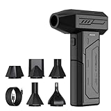
- Powerful Turbo Fan:CAGIWIRU Electric Air Duster have reached speed up to 130000RPM,Can efficient remove dust and debris.With LED light and Three Adjustable Speed to meet with different cleaning tasks.
- With Attached USB C Fasting Charging cable.Charing 3 hours,Enjoy up to 240 minutes of use on the lowest setting, For third speed can use for 25mins.with four charging options to meet with your needs.
- Wide Application: attached 5 different nozzles,making it suitable for a variety of scenes, such as car,pet, pc, keyboards, and other electronic devices. It also serves for office and home clean duster.
- Handy Design & Portable:Cordless air duster electric nozzle is Light weight and small size, design and comfortable to hold and space saving, convenient to carry around. You can put it in your room or inside the car without taking up space.
- Economical &Reusable: Built durable materials with a long-lasting battery,our CAGIWIRU air duster it's a sustainable alternative to disposable air cans.
For the equations below, d always means the center-to-center distance between neighboring cells. If a drawing gives the hexagon’s side length s, convert it first: d = sqrt(3) × s. Using the side length directly as the pitch produces a lattice that is too tight by a factor of sqrt(3).
Define the convention before calculating anything
Most conversion errors come from mixing conventions rather than from difficult arithmetic. Record these values in the project notes or in the generation script:
- Orientation: pointy-top or flat-top. This determines which basis vectors are used.
- Indexing: axial coordinates, or an offset row/column scheme such as odd-r, even-r, odd-q, or even-q.
- Pitch: the nearest-neighbor center spacing, with its unit.
- Origin: the Cartesian location
(x0,y0)assigned to lattice coordinate(0,0). - Axis direction: whether increasing y goes upward or downward in the editor or source drawing.
- Precision policy: how many decimal places are retained before final placement and manufacturing export.
Choose one convention and use it for both forward and inverse conversion. An origin shift or a 90-degree rotation is not a minor formatting change; it changes every coordinate.
The Tool Desk
Outbyte Driver Updater FREEFix the driver behind crashes, sound loss and screen glitchesFind Drivers →Outbyte PC Repair FREERepair Windows errors before they cause bigger problemsFix Now →Pointy-top hexagons: forward and inverse conversion
In the pointy-top convention, choose basis vector a = (d, 0) and basis vector b = (d/2, sqrt(3)d/2). Axial coordinate q counts steps along a, while r counts steps along b.
| Operation | Equation | Meaning |
|---|---|---|
| Hex to Cartesian x | x = x0 + d(q + r/2) |
Horizontal position after both lattice steps |
| Hex to Cartesian y | y = y0 + (sqrt(3)d/2)r |
Vertical component of the second basis direction |
| Cartesian to axial r | r = 2(y - y0)/(sqrt(3)d) |
Recover the second lattice coordinate |
| Cartesian to axial q | q = (x - x0)/d - r/2 |
Recover the first lattice coordinate |
Worked pointy-top example
Suppose the pitch is d = 2 mm, the lattice origin is (10 mm, 5 mm), and the target location is axial coordinate (q,r) = (3,-2). The forward transform gives:
Rank #2

- Screen Cleaner is Your Screen’s New Bestfriend! - EVEO is proud to present a screen cleaner that’s perfectly suited for your TV. Meet your new screen cleaner, computer screen cleaner, laptop cleaner, iPad cleaner, Macbook,tv cleaner or any other electronic device. Our screen cleaner spray and wipe along with the included plush microfiber cloth, easily removes dust, fingerprints & other smudges on the screen’s surface. Clean effectively for a streak-free screen
- Gentle on your Screens - Our screen cleaner spray and wipes is compatible to be used even for the most sensitive LCD, LED, CRT, and OLED screens in proper use. Be at ease knowing that this product is compatible with all the major brands: LG, SONY, Samsung, Sharp, iPad, iPhone, Android screens, Kindle, PC monitors - we’ve got you covered! Can be used as LCD screen cleaner, tv cleaner, smart tv screen cleaner, and more
- Premium Super Soft Plush Microfiber Cloth - Included in this efficient screen cleaning kit. This screen cleaner spray and wipe has our signature plush microfiber cloth specially designed to comply with screens and monitors and leave them streak-free. Has been shown to effectively absorbs stubborn stains, zero streaks, and no fiber shedding. Always use this together with our screen cleaner for the best results
- Easy-to-Use Screen Cleaner Kit + microfiber cleaning cloth - The EVEO Screen Cleaning Kit will easily be your new favorite tool when it comes to taking care of the things you love most, quick and easy solution for a streak-free screen. Simply screw on the sprayer gun on the screen cleaner bottle. Spray the cleaning liquid onto the microfiber cloth, then wipe the screen until desired cleanliness & shine is achieved.
- Quality Screen Care Kit Worth Purchasing - Enjoy a convenient Screen Cleaner anytime, anywhere you need it. Your satisfaction is our top priority. We stand behind the quality of our products and that’s why, you shouldn’t be worrying at all. We manufacture the Best Screen Cleaner. and can be used for laptop cleaning kit, laptop screen cleaner, tv screen cleaner for smart tv. MacBook screen cleaner, monitor cleaner or screen cleaner spray for electronic devices with microfiber cleaning cloth
x = 10 + 2(3 + -2/2) = 14 mm.y = 5 + (sqrt(3) × 2/2)(-2) = 1.535898 mmapproximately.
Entering approximately (14, 1.535898) mm in a Cartesian PCB editor places the point corresponding to that axial location. If the editor displays y downward, the screen direction may look inverted, but the same numerical transform remains valid once your chosen origin and axis signs are consistent.
Checking the inverse
Starting with (14, 1.535898), the inverse equations return r ≈ -2 and q ≈ 3. Keep extra digits during this check. Rounding the intermediate value of r too early can cause a later coordinate to land one lattice step away.
Flat-top hexagons: the rotated basis
Flat-top cells use basis vectors a = (sqrt(3)d/2, d/2) and b = (0,d). The same axial integers are valid, but their Cartesian interpretation is rotated relative to the pointy-top case.
| Operation | Equation | Meaning |
|---|---|---|
| Hex to Cartesian x | x = x0 + (sqrt(3)d/2)q |
Horizontal component of the first basis direction |
| Hex to Cartesian y | y = y0 + (d/2)q + dr |
Combined vertical components of both steps |
| Cartesian to axial q | q = 2(x - x0)/(sqrt(3)d) |
Recover the first lattice coordinate |
| Cartesian to axial r | r = (y - y0)/d - q/2 |
Recover the second lattice coordinate |
Worked flat-top example
Use the same origin and pitch as before, (x0,y0) = (10,5) mm and d = 2 mm, with (q,r) = (3,-2):
x = 10 + (sqrt(3) × 2/2) × 3 = 15.196152 mmapproximately.y = 5 + (2/2) × 3 + 2 × -2 = 4 mm.
These coordinates are correct for the flat-top basis and are not interchangeable with the pointy-top result. If a footprint pattern appears sheared or the rows drift diagonally, the usual cause is applying the formula for the other orientation.
Rank #3

- 【Large size】:Measuring 800 x 300 mm/ 31. 5×12 inches, which is wider and taller than others. Large mouse pad can perfectly fit your keyboard and mouse of any size, and there is also ample space for peripherals such as phones, tablets, etc.
- 【LED backlight mouse pad】:Blade Hawks RGB mouse pad provides 7 static modes and 7 dynamic modes will give you the options you are looking for. Power-off memory function remembers the last lighting mode you selected. The super glow fiber Chroma will give you a colorful gaming setup that you want.
- 【Anti-slip rubber base】:Made from Natural rubber, this gaming mousepad will firmly grip your desktop, allowing you to enjoy the ultimate precision in the games you are most passionate about. It also comes with a texture that enhances this ability even further.
- 【Smooth and waterproof surface】: Micro-textured cloth surface, for extremely precise mouse control and a smooth movement. When liquid splashes on the gaming mouse pad, it forms water droplets and slides down. Will not delay your work or gameplay.
- 【Plug and play】: This mouse and keyboard pad is powered by USB, plug and play, no driver required. One button control light modes. Press one time to change the lighting mode, press twice to change the brightness, press and hold about 3 seconds turn ON/OFF.
Axial coordinates versus staggered rows and columns
Axial coordinates are the least ambiguous representation for conversion because they are two integers tied directly to the chosen basis. Source drawings and spreadsheets often use a staggered row/column notation instead. A row may be shifted on every odd or every even index, so the visible column number is not automatically the axial q.
One common pointy-top offset convention
For an odd-r horizontal-row convention, where odd-numbered rows are shifted, a common conversion is:
q = col - (row - (row mod 2))/2r = row
For the corresponding even-r convention:
q = col - (row + (row mod 2))/2r = row
These formulas assume the row index starts at zero and that the source uses the stated horizontal-row definitions. A one-based spreadsheet, a vertically oriented layout, or a different meaning of “odd row” requires an adjustment. Convert a few known neighboring cells by hand before generating the complete board.
One common flat-top offset convention
Flat-top layouts are often expressed as staggered columns. In an odd-q convention, one common mapping is:
q = colr = row - (col - (col mod 2))/2
For an even-q convention:
q = colr = row - (col + (col mod 2))/2
Do not infer the offset rule from the word “staggered” alone. Ask which rows or columns are shifted, whether numbering starts at zero or one, and which direction is positive. Once the offset indices have been converted to axial (q,r), use only the pointy-top or flat-top equations appropriate to the physical pattern.
Windows Errors? Fix Them Before They Spread
Repair common Windows errors and clear accumulated junk for a smoother, more stable PC - no reinstall needed.Free scan · no reinstallCrashes, No Sound, or Screen Glitches?
Random freezes, missing sound and display glitches usually trace back to one bad driver. Find and replace yours safely.Free scan · under a minuteRank #4

- 【Softer and More Comfortable】Vaydeer wrist rest has unique diamond pattern, which is the combination of softness and aesthetics. The materials of wrist rest are improved into higher quality memory foam and covered with silky smooth lycra. The computer wrist rest makes you as comfortable and cushiony as like rest your wrists on clouds.
- 【Ergonomic Wrist Saver】The wrist rests for keyboard and mouse comes with a 17.32×3.15×0.83 inch keyboard wrist pad and a 5.94×3.15×0.83 inch mouse wrist support. Based on ergonomic design, the unique concave shape is the perfect fit for your wrist joints. The wrist rest pad fits most computer keyboards and laptops, improve hand and wrist posture, release your wrist and arm stress.
- 【Non-Slip Rubber Bottom】Featuring an anti-skid silicone base on the bottom, this wrist keyboard support stays firmly in place on your desk, preventing the padding from sliding around, ensuring stable and consistent wrist support during extended computer sessions.
- 【Better Experience & Pain Relief】Our keyboard arm rest is beneficial to alleviate the soreness caused by direct contact and friction between your arm and a hard desk surface, reducing the risk of wrist fatigue or carpal tunnel. The soft texture of memory foam can evenly distribute the pressure around your wrists and provide good support with just enough give.
- 【Helpful in Multiple Scenarios】Whether you're working, studying, writing, typing, gaming, this keyboard and mouse rest combo is an essential accessory to add comfort and support to your hands and wrists. It’s also a great gift for men, women, family, friend, coworker, gamer, teacher, etc.
A repeatable PCB conversion workflow
- Identify the source convention. Determine orientation, index type, pitch definition, units, origin, and axis direction. If a drawing gives side length rather than center pitch, calculate
d = sqrt(3)s. - Choose a stable origin. Use a datum that is easy to probe or identify, such as the first pad center, a board corner with a documented offset, or a mechanical mounting reference. Assign that point to
(0,0)or to its measured Cartesian location. - Convert indices to axial coordinates. If the source is staggered, apply its exact odd/even row or column rule first. Keep the result as integers.
- Apply the forward transform. Calculate x and y using the selected basis. Retain more decimal places than the editor’s display shows until the final entry or file generation step.
- Place the geometry. Enter the Cartesian values in the PCB editor’s coordinate fields or generate the footprint/pad positions programmatically. A rectangular snap grid can be left on for ordinary work, but it should not silently alter generated hex coordinates.
- Round-trip a sample. Convert several generated points back to lattice coordinates. Exact or near-integer results confirm that the origin, orientation, and pitch agree.
- Check physical spacing and staggering. Measure at least one neighbor in each basis direction. Each nearest-neighbor distance should be
d, and the expected half-pitch offset should appear in the appropriate direction. - Run design-rule checks. Coordinate correctness does not prove that copper clearances, courtyard spacing, drill constraints, or board-edge rules are satisfied. Run the editor’s design-rule checks after placement.
Using a Cartesian PCB editor such as KiCad
KiCad’s documentation describes a movable grid origin, Cartesian coordinate display, coordinate entry in inches, mils, and millimeters, and grid snapping. Its footprint-editor guidance describes setting the grid origin at the first pad and setting the grid size to the pad pitch. Those features make it practical to place a generated hex pattern, but they do not by themselves create a native hexagonal snap grid.
For a documented reference, see the KiCad 10 PCB Editor manual and the KiCad footprint editor guidance. The editor’s grid data structure also exposes separate x and y grid dimensions in the KiCad GRID API; that is different from defining six angular neighbor directions.
Practical KiCad sequence
- Set the project’s display units to the unit used by your transform, or convert every value consistently before entry.
- Move the grid origin to the chosen datum. In a footprint, placing the origin on the first pad makes inspection and subsequent pitch checks easier.
- Generate the pad or footprint coordinates externally or from a script, then enter the resulting x/y positions rather than trying to force a rectangular snap to approximate the lattice.
- Use a sufficiently fine grid, or disable snapping temporarily while entering exact coordinates, so the editor does not move a point to the nearest rectangular intersection.
- Inspect coordinate readouts for several corners and interior points. Compare them with independently calculated values before copying the pattern to a larger array.
- Restore the normal design grid for unrelated routing work and run design-rule checks on the completed board.
Exact menu labels and custom-snapping capabilities vary by editor and version. Confirm the controls in the version installed on the design workstation; the documented capabilities above support Cartesian placement, not a guaranteed built-in hex snap mode.
Generating coordinates instead of entering them by hand
Manual entry is reasonable for a handful of pads. For a full sensor array, via field, or repeated footprint, generate the coordinates so that one source of truth controls pitch, origin, and orientation. The following Python example generates pointy-top axial locations; it uses millimeters because the chosen pitch and origin are in millimeters.
What’s actually slowing this PC down?
Pick the symptom - the matching free tool is one click away.
import math

sqrt3 = math.sqrt(3)
d = 2.0
x0, y0 = 10.0, 5.0
locations = []

for q in range(-3, 4):
    for r in range(-2, 3):
        x = x0 + d * (q + r / 2.0)
        y = y0 + (sqrt3 * d / 2.0) * r
        locations.append((q, r, x, y))

for q, r, x, y in locations:
    print(f'{q},{r}: {x:.9f} mm, {y:.9f} mm')
The script deliberately prints nine decimal places. You may use fewer digits in the final PCB file if the fabrication tolerance and editor format justify it, but do not truncate early during intermediate calculations. Add checks to the generator for duplicate points, an expected count, and a maximum coordinate range so a bad index conversion fails before data reaches the board.
Best Value

- 【No Drill Mounted】Cable management tray can be assembled in as little as 3 minutes or less-simply. Side clips easily clampe the edge of desk, pass through the holes on the sides, and secure excess cables with baskets. Desk cable management supports inward or outward installation to meet your needs in different scenarios, and provides you with great convenience when collecting and organizing wires.
- 【Rubber Pad Protects Desk】Wire organizer under desk built-in soft rubber pads on the clamp protect your desk from scratches, so you will not damage your furniture or office.
- 【Sturdy and Beautiful】Cord management under desk is made of high-quality carbon steel and holds about 15 lbs. The wire basket has 2 holes on each side of the tray to enable your cables to pass freely. Cable baskets are suitable for desk thickness use from 0.4" to 2.4".
- 【Space Saving & Keep Organized】Desk cable management tray holds all your power cords, outlet strips, USB hubs and computer transformers hidden from your feet, and the data cables will not enter the vacuum cleaner to keep your desk clean and tidy. Desk wire organizer is also suitable for use in the kitchen and outdoors.
- 【Reduce Safety Risks】Cable tray under desk keeps all plugs away from your kids, no more worry about tripping. Using 2 holes wire tray saves extra space, helps you easily cabling and wire protection. The mesh design is not easy to accumulate dust, but avoids safety accidents caused by messy wires.
Converting measured x/y coordinates back to the nearest hex center
The inverse equations produce fractional q and r when a probe point, imported feature, or measurement falls between centers. If the goal is to identify the nearest valid hex location, do not round x and y independently. Independent Cartesian rounding generally moves the point to a location that is not on the lattice.
Hex-coordinate rounding method
- Apply the appropriate inverse transform to obtain fractional axial coordinates
(q,r). - Convert them to cube coordinates:
cx = q,cz = r, andcy = -cx - cz. - Round
cx,cy, andczto the nearest integers. - Compute each rounding error. If the largest error is on
cx, replace the rounded x value with-ry - rz; if it is oncy, replace y with-rx - rz; otherwise replace z with-rx - ry. - Use the corrected integer axial pair
(rx,rz)and run the forward transform to obtain the exact Cartesian center.
At an exact boundary between two centers, two answers can be equally near. Define a tie rule, such as choosing the lower q value, and use it consistently in inspection scripts and manufacturing documentation.
Precision, units, and snapping pitfalls
Premature rounding
The factor sqrt(3) is irrational, so most y coordinates are not short decimal fractions. Keep full floating-point precision or high-precision decimal values through index conversion and only round at the output boundary. A displayed value such as 1.536 mm may be adequate for a screen readout but insufficient for a tight-pitch footprint array.
Recommended Free Tools
Unit mismatches
Because the equations are linear, the same unit must be used for d, x0, y0, x, and y. Convert inches to millimeters or mils once, preferably at input, rather than mixing values in one formula. A factor-of-25.4 error can look like an origin mistake because the resulting pattern may still be internally regular.
Rectangular snapping
A rectangular snap grid can move a generated point independently in x and y. That destroys the exact relationship between the two basis directions, even when the visual displacement is small. Enter exact coordinates, use a finer grid than the required placement tolerance, or temporarily turn snapping off for generated locations.
Origin confusion
PCB tools may distinguish grid origin from page, drill, or placement origins. Changing the visible grid origin does not necessarily change existing footprint coordinates. Confirm which origin your coordinate entry uses and keep the transform’s (x0,y0) tied to the same physical datum.
Validation checklist and failure diagnosis
- Every point is shifted equally: check the origin offset or a swapped sign in
x0ory0. - Rows or columns drift diagonally: verify pointy-top versus flat-top formulas and confirm the source’s stagger direction.
- Neighbor distances are wrong by about 1.732: side length was probably used as center pitch, or vice versa.
- Only odd rows are displaced: inspect the odd-r/even-r or odd-q/even-q conversion and whether indexing starts at zero.
- Round-trip coordinates are not integers: use the same orientation, origin, and pitch in both directions; do not mix a pointy inverse with a flat forward transform.
- Points look correct before placement but move afterward: rectangular snapping or unit conversion in the editor changed the entered values.
- The pattern is mirrored: check the sign of the editor’s y axis and whether the source drawing is viewed from the opposite side of the board.
- Design-rule checks fail despite correct geometry: separate coordinate validation from electrical and mechanical rules; inspect clearances, courtyard overlap, drill sizes, and board-edge spacing.
Choosing an approach for your project
| Approach | Best use | Strength | Risk |
|---|---|---|---|
| Axial coordinates plus forward transform | New designs and scripts | One unambiguous pair of integer indices | Requires documenting orientation and origin |
| Staggered row/column conversion | Importing an existing drawing or spreadsheet | Matches how many arrays are visually specified | Odd/even and zero/one-based rules are easy to mix up |
| Manual Cartesian entry | A small number of pads or test points | No generator setup | Transcription and snapping errors increase with array size |
| Generated Cartesian coordinates | Large repeated arrays and revisions | Repeatable, auditable, and easy to regenerate after a pitch change | Requires a checked script and a controlled import or entry process |
For a fixed convention and origin, there is no competing “best” conversion algorithm. The transformation is determined by the selected basis. The meaningful decisions are which orientation and indexing convention match the source, how coordinates will be entered, and how much numeric precision the board requires.
Quick Recap
Final pre-release checks
- Write the orientation, pitch definition, units, origin, and index convention beside the generated coordinate list.
- Verify the side-length-to-pitch relationship if the mechanical drawing used hexagon side dimensions.
- Round-trip at least one point from each edge and one interior point.
- Measure neighbors in both basis directions and confirm the distance is
d. - Check that no rectangular snap operation changed generated values.
- Compare the first and last coordinates against the intended board outline and keepout regions.
- Run the PCB editor’s design-rule checks and inspect the fabrication output, not only the on-screen pattern.
Product prices and availability are accurate as of the date/time indicated and are subject to change. Any price and availability information displayed on Amazon at the time of purchase will apply.

