
Free tools Windows power users keep installed
One-click scans. No signup required.
iTechGuides is reader-supported. When you buy through links on our site, we may earn an affiliate commission. As an Amazon Associate I earn from qualifying purchases. Learn more
Do not wire a toy to Raspberry Pi GPIO until you know what the toy’s button or sensor is electrically connected to. A genuinely isolated switch can usually be read as a GPIO input with a defined pull-up or pull-down. A button embedded in a toy’s scanning circuit, or a sensor powered by the toy, may produce voltages that are unsafe for the Pi or may need isolation. Raspberry Pi GPIO uses 3.3-volt logic, so measure and verify the toy circuit first; use an appropriate interface for any incompatible signal, and keep motors and other loads behind driver circuitry.
The safe answer depends on the toy’s circuit
There is no universal Raspberry Pi-to-toy wiring diagram. The same plastic button can be either a passive contact that simply opens and closes a circuit or one part of a powered button matrix connected to a toy’s microcontroller. A “sensor” might provide a digital logic signal, an analog voltage, a pulse train, or a powered output with a voltage outside the Pi’s limits.
Start by identifying the exact Raspberry Pi model, the toy model, the battery or adapter voltage, and the wires or board traces connected to the control. Raspberry Pi’s official hardware documentation is the reference for the board’s electrical limits: Raspberry Pi hardware documentation. Do not rely on the toy’s label, wire color, or a connector’s shape as proof of compatibility.
Do these 3 things before closing this tab:
1Repair Windows errors before they cause bigger problems2Fix the driver behind crashes, sound loss and screen glitches3Clear out junk files and repair common Windows errors- Passive, isolated switch: normally suitable for a GPIO input after you establish a defined logic state.
- Powered or matrix-connected button: do not connect it directly until you understand the toy’s circuit and signal levels.
- Sensor output: verify supply voltage, output voltage, signal type, current, and grounding or isolation requirements.
- Motor, lamp, speaker, solenoid, or other load: do not drive it from a GPIO pin; use a suitable driver circuit.
Raspberry Pi GPIO limits you must respect
Current Raspberry Pi boards expose a GPIO header. The official documentation describes GPIO outputs as 3.3 V and GPIO inputs as 3.3 V-tolerant. That does not make every signal from a toy safe: a signal above the input tolerance, a negative excursion, or a powered circuit with an unexpected reference can damage the board.
#1 Best Overall
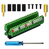
- The item has been soldered and assembled. Support for Raspberry Pi 1 Model B+, Pi 2 Model B, Pi 3 Model B, Pi 3 Model B+, Pi 4 Model B, Pi Zero, Pi Zero-W.
- Terminal block pitch 2.54mm/0.1", wire size range 28AWG to 18AWG, strip length 4.5mm, screw M1.6 steel, pin header and cage copper.
- FR-4 fiber glass PCB, dual copper layers.
- 2x20 positions header connect to Raspberry Pi board.
- Packing list: 1x terminal block breakout module, 4x M2.5x6mm screws, 4x 10mm nylon standoffs. 2x 11.5mm brass standoffs, 1x small slotted screwdriver (NOTE: the item not include Raspberry Pi Board).
| Fact | What it means for a toy connection |
|---|---|
| GPIO logic is 3.3 V | Design toy interfaces around 3.3-volt logic unless the exact board documentation and an interface circuit establish otherwise. |
| Inputs are described as 3.3 V-tolerant | Do not apply a higher-voltage toy output directly. Confirm the measured voltage under the toy’s normal powered conditions. |
| “Do not use 5V for 3.3V components.” | Never feed a toy’s 5-volt rail into a Pi GPIO or use 5 V as a GPIO pull-up. |
| Approximately 3 mA maximum per GPIO pin is cited for the Pi’s 3.3 V supply design | Treat this as a qualified design figure, not a universal continuous-current rating for every board or pin. Use conservative loads and consult the documentation for the exact model. |
| LEDs need current limiting | If an LED is part of your test circuit, include an appropriate series resistor; do not connect an LED directly to GPIO. |
| Motors must not be connected directly | Use an H-bridge or motor-controller board, with the motor supply separated from the logic pin as required by that driver. |
The approximately 3 mA figure describes the design of the Pi’s 3.3 V supply per GPIO pin in the cited documentation. It is not permission to force 3 mA through every external device, and it is not a guaranteed safe-current specification for all boards. The same documentation discusses pad-drive settings without establishing a blanket, guaranteed maximum safe current under every condition.
Keep the distinction between a logic signal and a load. A GPIO can command a driver, but the driver should provide the current for a motor, lamp, relay, speaker, or solenoid. A GPIO should not be used as a toy’s power source merely because the toy works at a similar nominal voltage.
Inspect the toy before making any connection
1. Record the hardware and power arrangements
- Write down the Raspberry Pi model and revision, and identify the header pins you intend to use by the board’s official pin documentation.
- Record the toy’s battery count, battery chemistry if known, external-adapter rating, and whether the toy has a USB, audio, serial, or other accessible connector.
- Photograph the toy’s wiring and circuit board before moving wires. Mark battery positive, ground, button traces, sensor wires, and motor wires.
- Disconnect the toy and the Pi from power while tracing conductors or checking continuity.
2. Decide whether the control is a bare switch
With all power removed, a simple mechanical switch will show an open circuit in one position and a low-resistance connection in the other. That test alone does not prove the switch is isolated: a button on a toy PCB can be connected to pull resistors, a scanned row or column, an LED, or a microcontroller input.
What’s actually slowing this PC down?
Pick the symptom - the matching free tool is one click away.
Trace both sides of the button to the board. If either side runs into an integrated circuit, a resistor network, a diode, an LED, or a shared row/column of other buttons, treat it as an active circuit rather than a free-standing contact. Do not assume that replacing the toy’s button with a Pi GPIO wire is electrically equivalent to pressing it.
3. Identify sensor signal characteristics
For every sensor wire, establish four things before connection:
Rank #2

- Compatible models: Raspberry Pi 5 / 4B / 3B+ / 3B / 3A+ / 2B / 1B+ / 1A+ / Zero 2 W / Zero W / Zero (Note: NOT compatible with 500 / 400)
- GPIO status LED: LED on if GPIO outputs / inputs high level, LED off if GPIO outputs / inputs low level
- Independent LED: The status LED is driven by the chip instead of the GPIO so the GPIO will not be affected
- Terminal block and header: Connect to all pins of the main board, 2.54 mm (0.1 inch) pitch
- Pin name: The BCM numbering name of each pin is printed next to it
- Supply: what voltage powers the sensor, and does that supply remain present when the toy is idle?
- Output range: the lowest and highest voltage measured relative to the sensor’s ground while the toy operates normally.
- Signal type: steady digital level, changing analog voltage, pulses, frequency, or a bidirectional bus.
- Reference and isolation: whether the sensor ground can safely be connected to Pi ground, or whether the circuits must remain isolated.
Measure at the toy’s normal battery or adapter voltage, not only from a bench supply set to a convenient value. A sensor output can change when a motor starts, when a button is pressed, or when the toy enters a different operating mode.
Measure first, connect second
A multimeter is useful for establishing voltage relationships, but it is not a substitute for a schematic when the toy contains a fast or bidirectional digital interface. Work with the Pi completely disconnected from the toy during the initial measurements.
- Power off and inspect: look for damaged insulation, corrosion, loose battery contacts, and wires that could short against the toy chassis.
- Check continuity: identify the two conductors that change state when a genuinely passive button is pressed. Do not inject voltage during this test.
- Power the toy as intended: use its normal batteries or approved adapter. Keep the Pi disconnected.
- Establish the reference: measure each candidate signal against the toy’s circuit ground. Do not assume the black wire is ground; verify it on the board.
- Measure both states: record the signal with the button released and pressed, or with the sensor in its relevant minimum and maximum conditions.
- Watch transitions: note whether the signal exceeds 3.3 V, falls below ground, or changes when a motor, light, or audio circuit activates.
- Power down before rewiring: never move jumper wires on an energized, uncertain circuit.
If the toy circuit and Pi will share a ground, connect that ground only after confirming that neither device has a conflicting power supply or an unsafe voltage on the signal. If a shared ground is undesirable or impossible, choose an interface that provides the required isolation rather than improvising a connection.
Connection pattern: a genuinely isolated button
For an isolated, two-terminal switch, the usual arrangement is to connect one terminal to a suitable logic reference and the other to a GPIO input, with a defined pull-up or pull-down. Raspberry Pi documentation notes that internal pulls can establish a known input state. In one polarity, an open switch reads the pulled state and a closed switch changes it; in the opposite polarity, the logic is reversed.
The important word is isolated. A toy button that is already wired into a powered board is not automatically a dry contact. If you cannot demonstrate that the two terminals are independent of the toy’s electronics, stop and analyze the board instead of copying this pattern.
Rank #3

- Designed for Raspberry Pi A+/B+/3 B/4/4B
- This shield is in a fancy T-shape, coming with 40 pins, can plug into any solderless breadboard
- High quality Solderless Breadboard: 400 tie-points
- 22cm rainbow ribbon cable with socket, easy to connect GPIO breakout with your Pi.
- Technical support is available at any time!
Bring up the switch safely
- Leave the toy’s original electronics disconnected from the button, if and only if the circuit can be separated without damaging or defeating a required return path.
- Connect the button and Pi ground according to the chosen pull-up or pull-down arrangement. Do not use a 5 V rail.
- Configure the selected GPIO as an input with one defined internal pull, or use an external resistor chosen for the known circuit. Do not leave the input floating.
- With no button press, verify that the software reports one stable state.
- Press and release the button repeatedly while watching the input. Mechanical contacts can bounce, so software may need debouncing; do not interpret a few rapid transitions as additional intentional presses.
- Disconnect power before changing the wiring or moving the input to another header pin.
Do not publish or follow a universal pin-number or resistor diagram for an unspecified toy. The correct header pin, pull direction, and external resistor depend on the Pi model, the switch circuit, wire length, and electrical noise in the toy.
The Tool Desk
Outbyte PC Repair FREEClear out junk files and repair common Windows errorsFree Scan →Outbyte Driver Updater FREEScan for outdated or missing drivers - takes under a minuteDriver Scan →When the toy’s original button circuit must remain in place
Many toys scan buttons by driving one conductor and reading another, or use a controller that expects a particular voltage or timing. In that situation, placing a Pi GPIO directly across the button can short two driven outputs, inject a wrong voltage, or corrupt the toy’s controller.
First determine what appears on each button terminal while the toy is powered and operating. If the signal is incompatible with 3.3 V GPIO, use an interface designed for the measured voltage, direction, speed, and current. Depending on the known circuit, that may involve level translation, a transistor stage, or optical isolation. A generic “logic-level converter” or “opto-isolator” is not automatically correct: some are one-directional, some require a shared ground, and some do not pass slow, fast, analog, or bidirectional signals in the way your toy needs.
The safest control strategy is often to sense the toy’s button event without taking over its electrical node, or to emulate a button through a properly selected isolated switch interface. Choose only after you know whether the node is pulled high, pulled low, scanned, multiplexed, or driven actively.
Connecting a sensor output
Digital sensor output
A digital output can connect directly only when its high and low levels, reference ground, direction, and current are compatible with the Pi input. Measure the output while the sensor is operating, including its startup and fault states. A signal that is normally 3.3 V can still become unsafe during a different mode or when the toy’s battery is freshly charged.
Crashes, No Sound, or Screen Glitches?
Random freezes, missing sound and display glitches usually trace back to one bad driver. Find and replace yours safely.Free scan · under a minuteWindows Errors? Fix Them Before They Spread
Repair common Windows errors and clear accumulated junk for a smoother, more stable PC - no reinstall needed.Free scan · no reinstallRank #4

- Easy GPIO Access: G469 breakout board for quick access to Raspberry Pi GPIO pins, Model: G469
- Broad Compatibility: Compatible with Raspberry Pi 5 / 4B / 3B+ / 3B / 2B / Zero 2W and other models
- Clear Labeling: Includes pin labels and stickers for easy identification and wiring
- Industrial Quality Terminals: Reliable, high-quality terminals ensure stable connections
- Packing List: 1 x G469 GPIO Terminal Block Breakout Board
Configure the Pi input before applying the signal, keep the input’s pull configuration compatible with the sensor’s output, and avoid simultaneously enabling a toy pull-up and a conflicting Pi pull-down. If the sensor can drive the line in both directions, treat it as a bus and select a circuit that supports that behavior rather than wiring two outputs together.
Analog, pulse, or unknown output
A changing voltage is not automatically a digital GPIO signal. Establish whether the toy is producing an analog level, a pulse frequency, a serial stream, or a signal that changes polarity. GPIO alone should not be asked to interpret an unknown analog or bus signal directly. Select a converter or interface only after the voltage range, timing, direction, and grounding requirements are documented for that sensor.
Sensor power
Do not power a toy sensor from the Pi simply because the connector fits. Confirm the sensor’s required supply, startup current, and ground arrangement. If the toy’s sensor supply is noisy or switches with the toy’s motor, isolate or regulate the sensor side as required by the measured circuit.
Motors, lights, speakers, and other loads
A GPIO pin is a control signal, not a motor supply. Raspberry Pi’s documentation states: “Do not connect motors directly to the GPIO pins, instead use an H-bridge circuit or a motor controller board.” Use a driver whose logic input accepts the Pi’s 3.3 V signal and whose output stage is rated for the toy motor’s voltage and stall current.
Keep the motor’s supply current out of the GPIO path. Motors can create electrical noise and voltage spikes when they start, stop, or reverse; the chosen driver and wiring must address those effects. If the toy has a lamp, speaker, relay, or solenoid instead of a motor, apply the same principle: select a driver for that load rather than connecting the load to a header pin.
Best Value

- Cables Wire Size: Length: 8.26"/21cm, Width: 2.16"/5.5cm;T Type GPIO Adapter: 28.74"x23.22"/73 x 59cm
- Strong Compatibility: Suitable for 4B, consistent interface, and compatible with Rpi3B+/Rpi3B/2B/Zero/Zero W/Zero WH
- Advantage: GPIO connection is convenient for you to connect with GIPO, which can be applied to breadboard experiments. Note that the T-type expansion board interface corresponds to the GPIO interface
- Application: It can be used for pin expansion of the experiment board, adding experiment items, etc., and can be connected to the pin very reliably without soldering
- Colorful design, 40P color, 40 in a row
For a simple LED test, use a series current-limiting resistor and remain within conservative GPIO current limits. The Pi’s approximately 3 mA per-pin supply design figure is not a target brightness setting and does not replace the requirements of the LED or driver circuit.
Independent reader supportYour contribution helps us test, update, and keep practical guides available for everyone.Choosing an interface without guessing
| Known toy-side condition | Likely approach | Information still required |
|---|---|---|
| Two-terminal, isolated mechanical switch | GPIO input with a defined internal or external pull-up/pull-down | Switch isolation, desired logic polarity, cable length, and debounce behavior |
| 3.3 V-compatible digital sensor with shared reference | Direct GPIO input, subject to verified levels and direction | High/low limits, startup behavior, output current, and noise |
| Higher-voltage or negative-going output | Level interface or isolation selected for that voltage | Maximum and minimum voltage, speed, polarity, and whether bidirectional operation is needed |
| Button in a scanned or actively driven matrix | Purpose-built switching or isolation interface after tracing the matrix | Drive timing, pull networks, row/column behavior, and safe injection point |
| Motor or other power load | H-bridge, motor controller, transistor, or other load driver | Load voltage, startup/stall current, direction control, and power-supply arrangement |
A GPIO breakout board can make header pins easier to access during prototyping, but it does not automatically add level shifting, current limiting, or protection. Treat it as a mechanical convenience unless its documentation explicitly provides the interface functions you need.
A controlled first-power-up procedure
- Bench-test the interface alone. Use a known, safe signal source or a disconnected switch before attaching the toy’s powered board.
- Set the Pi input first. Configure the selected GPIO as an input with the intended pull state while the toy signal is still disconnected.
- Confirm grounds and supplies. Recheck polarity, measured voltage, and whether the toy and Pi are meant to share a reference.
- Insert protection or translation. If the measured toy signal is outside GPIO limits or requires isolation, install the chosen interface before connecting the Pi.
- Connect with power removed. Make one connection at a time and inspect for shorts or accidental links to 5 V.
- Power the Pi and observe the idle state. If the input is already active, floating, or unstable, shut down and investigate rather than continuing.
- Power the toy in its normal sequence. Watch the input during startup, button presses, sensor changes, and motor operation.
- Test one function at a time. Verify sensing before attempting to control an actuator, and verify an actuator driver with the toy load disconnected first.
Common failure modes and fixes
| Symptom | Probable cause | Corrective action |
|---|---|---|
| Pi reboots when the toy starts | Motor or audio current is entering the Pi supply or ground | Separate the load supply, use the proper driver, improve grounding, and remove the load from GPIO. |
| Input changes randomly | Floating input, long noisy wire, or an undefined toy state | Use a defined pull-up or pull-down, shorten or shield wiring where appropriate, and verify the toy circuit. |
| Input reads high even when the button is released | The toy’s pull-up or controller is driving the button node | Do not parallel the Pi blindly; trace the node and choose a compatible interface. |
| Pi GPIO voltage is above 3.3 V | Toy rail or signal is being applied directly | Disconnect immediately and add a correctly specified level interface; never use 5 V on a 3.3 V GPIO. |
| Toy stops responding after wiring | Two active outputs were shorted, or a matrix line was loaded | Remove the connection, restore the original circuit, and analyze the button scan or controller node. |
| One press produces several events | Mechanical switch bounce | Debounce in software or with an interface designed for the switch; confirm the electrical state is otherwise safe. |
| Sensor works only while a motor is off | Supply noise, ground bounce, or an incompatible shared supply | Measure during motor operation and redesign the power, grounding, or isolation arrangement. |
Stop conditions: when not to proceed
- You cannot identify the toy-side ground or the voltage on the candidate signal.
- The signal exceeds 3.3 V, goes below ground, or changes in a way your proposed interface does not support.
- The button is part of a matrix or controller circuit and you have not determined which lines are driven.
- The proposed connection would put a motor, lamp, speaker, relay, or solenoid current through GPIO.
- The toy and Pi use separate supplies with an unknown relationship between their grounds.
- A measurement is inconsistent, the toy is damaged, or the wiring diagram conflicts with what you observe.
At any stop condition, disconnect the Pi and document the circuit before choosing a level translator, transistor stage, driver, or isolator. The exact component cannot be selected responsibly from the toy’s name alone; its voltage range, signal direction, speed, current, and isolation needs must match the measured circuit.
Recommended Free Tools
Practical checklist
- Exact Pi model and header pin identified.
- Toy power source and circuit ground verified.
- Button classified as isolated switch or active/matrix node.
- Sensor supply, output range, signal type, and direction measured.
- No 5 V signal or supply is connected to a 3.3 V GPIO.
- GPIO is configured as an input with a defined pull state before testing.
- Shared ground is intentional, or an appropriate isolation method is installed.
- Motors and other loads use a suitable driver, not a GPIO pin.
- LED test circuits include current limiting.
- First power-up is performed with one verified function at a time.
Following this process lets a Pi observe a toy without treating an unknown toy circuit as a simple switch. When the measured electrical conditions do not match the Pi’s 3.3 V GPIO requirements, the safe connection is an interface designed for those conditions—not a direct jumper wire.
Quick Recap
Product prices and availability are accurate as of the date/time indicated and are subject to change. Any price and availability information displayed on Amazon at the time of purchase will apply.

