
Do these 3 things before closing this tab:
1Scan for outdated or missing drivers - takes under a minute2Repair Windows errors before they cause bigger problems3Fix the driver behind crashes, sound loss and screen glitchesiTechGuides is reader-supported. When you buy through links on our site, we may earn an affiliate commission. As an Amazon Associate I earn from qualifying purchases. Learn more
There is no universal “bandwidth per GPU” or latency number for a multi-datacenter cluster. Size the network from the workload’s communication pattern, then design around the slowest link that a collective or serving request must cross. Keep tightly synchronized GPU traffic on the local GPU and cluster fabrics whenever possible; treat the inter-datacenter path as a separate tier with its own capacity, latency, failure and congestion budget.
Use separate paths for GPU collectives, storage, management and front-end traffic where the platform permits. Specify sustained throughput, burst behavior, loaded and tail latency, bisection capacity and failure-mode capacity. Finally, validate the complete software and network stack with representative NCCL collectives and application traffic. A port-speed specification by itself does not prove useful training throughput.

Start by drawing the network domains
A multi-datacenter GPU system is not one uniform network. Different traffic classes have different locality and performance requirements, and treating them as a single fabric makes capacity planning and troubleshooting harder.
What’s actually slowing this PC down?
Pick the symptom - the matching free tool is one click away.
Within-server scale-up
NVLink or another server-local interconnect carries the highest-frequency GPU-to-GPU exchanges. Tensor, pipeline and model-parallel operations may stay here, depending on how the application is partitioned. This tier normally has much lower latency and higher effective bandwidth than any Ethernet or InfiniBand link leaving the server.
#1 Best Overall

- Compatible with NVIDIA ConnectX-8 VPI Adapter, 800G OSFP, 1-Port, PCIe6.0 x16 Secure Boot Infiniband & Ethernet RoCE
Cluster scale-out
GPU NICs and switches connect servers inside a rack, pod or datacenter. NVIDIA’s DSX architecture describes this cluster interconnect as configurable for Ethernet or InfiniBand. Google’s compute-domain description separates scale-up from east-west accelerator scale-out. All-reduce, all-gather and reduce-scatter operations that fit inside one site should use this tier rather than the site-to-site link.
Inter-datacenter connectivity
A wide-area or metro link connects sites. It has different round-trip time, failure modes, routing and capacity than the local fabric. A training job that places a synchronized collective across this boundary can be limited by the slowest site link or by its tail latency, even when every local switch is non-blocking.
North-south, management and storage paths
Front-end requests, control traffic, image distribution, checkpoints and dataset reads compete for resources unless they are isolated. Google documents separate GPU and host/storage paths in its platform-specific GPU networking designs. Follow the same principle on bare metal when the hardware and operating system support independent interfaces, rails, VLANs or virtual networks.
| Domain | Typical traffic | Primary design objective |
|---|---|---|
| Scale-up | Intra-server tensor or pipeline exchanges | Highest local bandwidth and lowest latency |
| Local scale-out | Collectives among servers in a site | High bisection bandwidth, predictable hops and congestion control |
| Inter-datacenter | Cross-site synchronization, replication or federated serving | Explicit capacity, latency and failure budget; minimize bytes sent |
| Storage and host | Checkpoints, datasets, container images and logs | Isolation so I/O bursts cannot delay collectives |
| Front-end and management | Client requests, orchestration and monitoring | Security, availability and operational reachability |
Before selecting hardware, label every major message by the smallest domain it must cross. This map is more useful than an aggregate “cluster bandwidth” figure because it reveals which traffic can remain local and which traffic is hostage to the inter-datacenter path.
How much bandwidth does a multi-node GPU cluster need?
Calculate bandwidth from measured or estimated bytes exchanged during the communication phase and the time available for that exchange. For a phase that sends B bytes in T seconds, the minimum useful throughput is B/T. Add headroom for protocol overhead, concurrent jobs, burstiness and the performance you need after a link, rail or plane fails. This is a workload calculation, not a rule such as “one terabit per GPU.”
Rank #2
Inventory the demand
- Record message bytes per training step or serving request for all-reduce, all-gather, reduce-scatter, parameter exchange, activation exchange and sharding.
- Measure how much of each exchange stays inside a server, rack, site or region.
- Count simultaneously active jobs and whether they synchronize at the same time.
- Include checkpoint writes, dataset reads, image pulls and monitoring traffic during their largest bursts.
- Document endpoint injection bandwidth as well as switch bisection bandwidth. A large core fabric cannot compensate for an undersized GPU NIC or host bus.
Use an explicit capacity model
For each network tier, create a row with peak bytes, sustained bytes, allowed communication time, number of concurrent flows and the capacity remaining after a failure. Compare the resulting demand with both link rate and achievable application throughput. Account for encoding, packet headers, PCIe or memory-copy limits and the fact that collective algorithms do not always use a link at its line rate.
A simple illustrative calculation shows the method: if a hypothetical job must exchange 20 GB during a 0.25-second communication window, its arithmetic demand is 80 GB/s, or about 640 Gb/s before overhead and safety margin. That number is only an example of the calculation; it is not a recommended requirement for a particular model or GPU.
Do not generalize vendor scale figures
Google reports 47 petabits per second of non-blocking bisection bandwidth for one Virgo fabric linking 134,000 TPU 8t chips, and says a TPU 8t accelerator provides up to four times the bandwidth of its previous generation. NVIDIA’s NVL72 reference design names an 800 Gb/s ConnectX-8 GPU interface split into two independent 400 Gb/s planes. These are architecture figures for the named systems, not portable bandwidth targets.
The useful question is whether your workload’s busiest cut in the topology has enough capacity under normal operation and under the planned failure case. A fabric can have impressive aggregate bandwidth while a rail, uplink or inter-site circuit becomes the bottleneck for a particular placement.
Set latency as a distribution, not a single number
Synchronous training advances when the slowest participant finishes its collective. Average unloaded latency therefore hides the condition that matters: loaded latency and its tail during real traffic. A congested queue, a longer route or a noisy storage burst can make one rank a straggler and hold every other rank at the barrier.
Rank #3

- Graphics Processing Unit (GPU)/Clock Speed Powered by the NVIDIA GeForce RTX 4080 SUPER graphics processing unit (GPU) with a 2.55 GHz boost clock speed. * On-board Memory 16GB GDDR6X * Interface Compatibility PCI Express 4.0 and earlier PCI Express 3.0. Offers compatibility with a range of systems. * Technologies 10,240 NVIDIA CUDA Cores, 2.55 GHz Boost Clock, 3rd Gen Ray Tracing Cores, 4th Gen Tensor Cores, NVIDIA DLSS, GameReady and NVIDIA Studio Drivers, NVIDIA GeForce Experience, NVIDIA G-SYNC, NVIDIA GPU Boost, GDDR6X Graphics MemoryPCI Express Gen 4 * Microsoft Direct 12 Ultimate, Vulkan RT APIs
Measurements to capture
- Round-trip and one-way latency at idle, at expected load and during burst traffic.
- High-percentile latency, not only the mean; record p95, p99 or the percentile your service-level objective uses.
- Collective completion time for the actual tensor sizes used by the model.
- Training step time, samples per second or serving tokens per second while the network is loaded.
- Latency when one path, rail, plane or circuit is removed.
Google describes millisecond-scale bursts and stragglers as concerns for synchronized training and reports lower unloaded latency for its flatter Virgo fabric than for an earlier generation. Those are platform statements, not universal latency thresholds. Set your own budget from the maximum step-time increase you can tolerate and verify it with the application.
Choose a topology by traffic pattern and failure behavior
The practical comparison is not simply “fat tree versus another topology.” Examine reachable bandwidth, hop count, bisection behavior, oversubscription, rail or plane alignment, fault isolation, observability and the way the design expands.
Rail-aligned, multi-plane non-blocking fabric
NVIDIA’s NVL72 reference uses a rail-optimized, full non-blocking fat-tree and two independent compute planes. Its 800 Gb/s interface is split across two 400 Gb/s planes, allowing traffic to be balanced. The reference also states that loss or degradation of a plane reduces available bandwidth. This behavior belongs to that design; do not assume every dual-port or dual-plane network fails or balances in the same way.
Flat, high-radix non-blocking fabric
Google describes Virgo as a flat two-layer non-blocking fabric using high-radix switching to reduce network tiers. Fewer tiers can reduce hop count and simplify the path for some traffic patterns, while the scale and port count impose their own design and operational constraints. Virgo is a Google TPU architecture example, not proof that a flat fabric is optimal for every GPU cluster.
| Decision axis | Rail-aligned multi-plane design | Flat high-radix design |
|---|---|---|
| Locality | Aligns GPU rails and independent planes to spread flows | Uses a shallow hierarchy to reduce tiers |
| Failure isolation | A failed plane can be isolated, with reduced aggregate capacity | Depends on switch and link redundancy in the particular build |
| Scaling | Expands by adding aligned rails, leaves and spines | Expands within the limits of high-radix switch ports and the two-layer plan |
| Operational concern | Placement and rail mapping must remain correct | Large switch domains require careful capacity and fault-domain planning |
| Evidence scope | NVIDIA NVL72 reference behavior | Google Virgo architecture description |
For either topology, calculate the bisection available to the largest job, the oversubscription at every tier and the capacity left after the largest single failure you intend to withstand. Check that the scheduler places ranks so their rails and switches do not converge on one oversubscribed link.
Rank #4
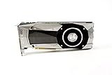
- Item Package Dimension -10.699999989086L X 3.699999996226W X 2.49999999745H Inches
- Item Package Weight - 2.1495070545 Pounds
- Item Package Quantity - 1
- Product Type - Video Card
Design the inter-datacenter tier separately
Cross-site communication should be minimized, aggregated and scheduled deliberately. NVIDIA’s NCCL discussion distinguishes a homogeneous case, in which InfiniBand or RoCE is used within and between datacenters, from a heterogeneous case, in which each site uses InfiniBand or RoCE and TCP connects the sites.
Keep frequent collectives inside a site
Place replicas, pipeline stages or shards so that the most frequent exchanges remain local. Use the site link for operations that are naturally less frequent, such as checkpoint replication, asynchronous parameter synchronization or request routing, unless the algorithm genuinely requires synchronous cross-site progress.
Compose collectives for a slow or narrow site link
NVIDIA describes composing reduce-scatter, an inter-datacenter all-reduce and all-gather so that more bytes are exchanged on intra-datacenter networks and fewer bytes traverse the site boundary. The exact algorithm, NCCL version and deployment support must be verified before committing to it; a topology-aware collective feature is not a guarantee that every software release or network combination will use the desired path.
Size the site link for the worst required phase
List the cross-site bytes for every phase, then compare them with the circuit’s sustained capacity, burst allowance and loaded latency. Include maintenance reroutes, provider rate limits, encryption overhead and the loss of one circuit if the design promises continued training. If the resulting communication window is unacceptable, change placement or parallelism before buying a larger local fabric.
Quick wins for a faster PC:
Scan for outdated or missing drivers - takes under a minuteDriver Scan →Clear out junk files and repair common Windows errorsFree Scan →Fix the driver behind crashes, sound loss and screen glitchesFind Drivers →InfiniBand or RoCE?
Both are documented options for GPU cluster interconnects. There is no neutral cost study or universal technology winner in the available evidence, so evaluate the complete stack rather than the protocol name.
Best Value

- NVIDIA GeForce RTX 4060Ti Founders Edition
- VIDEO_CARD
- generisch
| Criterion | InfiniBand | RoCE (RDMA over Converged Ethernet) |
|---|---|---|
| Local collective performance | Measure with the selected GPU, HCA, switches and NCCL build | Measure with the selected NICs, Ethernet switches and congestion configuration |
| Operations | Assess fabric management, routing, telemetry and staff expertise | Assess lossless or low-loss configuration, priority flow control, ECN and buffer tuning |
| Inter-site compatibility | Confirm that the provider or carrier can extend the required fabric semantics | Confirm MTU, QoS, congestion control and routed-domain behavior across sites |
| Failure behavior | Test path failover and degraded-fabric throughput | Test congestion spreading, queue recovery and link or switch failure |
| Cost and supply | Use a site-specific bill of materials and support model | Use a site-specific bill of materials and support model |
Run identical collective and application tests on both candidates when practical. Compare achieved all-reduce and all-gather time, tail latency under background traffic, operational telemetry and recovery time, not just advertised port speed.
Independent reader supportYour contribution helps us test, update, and keep practical guides available for everyone.Prevent storage and management traffic from slowing collectives
Use independent physical interfaces, rails, switches or virtual networks for GPU traffic and host/storage traffic when the platform supports them. Apply explicit QoS and queue policies where separation is logical rather than physical. Reserve management paths so that a data-plane incident does not remove administrative access.
Check hidden sharing points
- PCIe root complexes and host memory buses can be shared even when NICs have separate ports.
- Top-of-rack uplinks may carry both storage and GPU traffic unless the cabling and VLAN design prevent it.
- Container or VM networking can add a path that bypasses the intended GPU rail.
- Checkpoint storms can synchronize thousands of writes and fill buffers that collectives need.
- Monitoring, image distribution and data prefetching should be rate-limited during training windows.
Google’s platform documentation describes separate GPU and host/storage networking and publishes NCCL/gIB tests on named A3 Ultra systems with and without noisy background traffic. Treat those results as platform-specific examples; reproduce the test with your own images, drivers, NCCL release, topology and workload.
A practical design and validation workflow
- Characterize the workload. Record model size, parallelism dimensions, tensor sizes, collective frequency, checkpoint cadence, serving fan-out and the phases that can cross a site boundary.
- Map locality. Draw server, rack, site and inter-site edges. Mark every message that must cross each edge and identify the slowest edge.
- Set measurable objectives. Define step-time or tokens-per-second targets, sustained throughput, burst duration, loaded-latency percentiles and the acceptable degradation after a planned failure.
- Build the local fabric. Select InfiniBand or RoCE, NIC rate, switch radix, rail mapping and oversubscription from the measured demand. Verify endpoint injection and bisection capacity separately.
- Design the site link. Choose homogeneous or heterogeneous connectivity, route only the traffic that must cross sites, and document encryption, MTU, QoS, provider limits and failover.
- Configure isolation. Separate GPU, storage, management and front-end paths. Apply queueing and rate limits to background flows.
- Validate collectives. Run NCCL tests across one server, one rack, one site and all sites. Use the tensor sizes and rank counts that match production, then repeat with background storage and front-end traffic.
- Validate the application. Measure step time, throughput, GPU utilization and tail latency while the network is loaded. A microbenchmark that passes while the model stalls is not a successful design.
- Exercise failures. Remove a link, rail, plane, switch path or site circuit according to the stated failure model. Confirm that jobs fail over, degrade within budget or stop cleanly rather than silently producing corrupted results.
- Record a capacity runway. Document the next expansion point, the remaining bisection and site-link headroom, and the thresholds that trigger another pod, circuit or datacenter.
Common bottlenecks and recovery actions
| Symptom | Likely cause | Checks and corrective action |
|---|---|---|
| High GPU idle time during all-reduce | Oversubscribed uplink, poor rank placement or slow NIC injection | Inspect per-link counters and rank-to-rail mapping; rebalance placement or add capacity at the constraining tier |
| Good idle latency, poor production step time | Queueing from storage or another job | Repeat tests under representative background traffic; isolate paths and tune QoS |
| Only cross-site jobs are slow | Site-link bandwidth, RTT or collective algorithm is limiting progress | Measure cross-site bytes and loaded tail latency; keep more communication local or use a supported topology-aware collective |
| Performance drops sharply after maintenance | Lost rail or plane leaves insufficient residual bandwidth | Test the degraded topology in advance and size normal operation with the failure reserve included |
| Throughput varies by job placement | Nonuniform paths or switch hot spots | Compare placements, inspect bisection and enforce topology-aware scheduling |
| Storage bursts correlate with collective stalls | Shared NIC, uplink, buffer or host bus | Move storage traffic to a separate path or cap its rate; verify host and PCIe contention |
What a defensible capacity document contains
- A traffic matrix showing bytes, frequency and locality for every communication class.
- Per-tier sustained and burst capacity, endpoint injection rates, bisection bandwidth and oversubscription.
- Loaded latency distributions and application-level throughput targets.
- The selected topology, rail or plane mapping, switch tiers and expansion path.
- Inter-datacenter routing, collective behavior, QoS, encryption and provider limits.
- Isolation boundaries for GPU, storage, management and front-end traffic.
- NCCL and application test results with software versions, rank counts, message sizes and background-load conditions.
- Failure-test results and the remaining capacity after each stated fault.
Google Cloud’s Virgo article, dated April 22, 2026, describes its architecture as “three distinct and specialized layers that operate as one unified compute domain.” That principle is useful beyond that platform: make each layer’s role explicit, then validate the hand-offs between them.
Quick Recap
Product prices and availability are accurate as of the date/time indicated and are subject to change. Any price and availability information displayed on Amazon at the time of purchase will apply.

