
Do these 3 things before closing this tab:
1Fix the driver behind crashes, sound loss and screen glitches2Clear out junk files and repair common Windows errors3Scan for outdated or missing drivers - takes under a minuteiTechGuides is reader-supported. When you buy through links on our site, we may earn an affiliate commission. As an Amazon Associate I earn from qualifying purchases. Learn more
A practical starting point is an Arduino Nano 33 BLE Sense connected to a MAX30100 optical pulse-oximetry sensor. Read the sensor on the microcontroller, expose the results as Bluetooth Low Energy (BLE) characteristics, and inspect them on a phone with an app such as nRF Connect. Treat the result as an experimental wearable, not a medical monitor: the reference project reported implausible early readings and does not establish clinical accuracy or battery life.
What the reference wristband measures—and what it demonstrates
A Hackster project published May 26, 2023 describes a student prototype intended for extended, real-time monitoring of heart rate (HR), heart-rate variability (HRV), SpO₂, body or skin temperature, and whether the band is being worn. Its named optical sensor is a MIKROE MAX30100 PPG module, paired with an Arduino Nano 33 BLE Sense.
The demonstrated data path is optical sensor → microcontroller sampling and processing → BLE characteristics → phone app, with optional serial output for logging. The project authors used nRF Connect to view live values and PuTTY to capture serial CSV data. The work is useful as a prototype pattern, but it does not establish that every intended measurement was reliably implemented or validated.
Which parts do you need?
- Controller: Arduino Nano 33 BLE Sense, the board used in the reference build and the source of its BLE connection.
- Optical sensor: MIKROE MAX30100 PPG module for pulse-related and blood-oxygen estimates.
- Power: the reference used a 1000 mAh battery, a mini-USB charging module, and a 3.3 V Pololu regulator.
- Prototype and wearable hardware: breadboard and jumper wires for initial development, followed by a compact PCB and a strap or enclosure if the circuit is ready to wear.
- Phone and logging tools: nRF Connect for BLE inspection and a serial terminal such as PuTTY for CSV capture.
Do not assume that any MAX30100 breakout, charger, or regulator has the same pinout or electrical behavior as the parts in the project. Check the documentation for the exact modules you have and confirm supply voltage, signal compatibility, and grounding before connecting them. The reference parts list does not provide enough wiring detail to prescribe a universal pin-by-pin diagram.
#1 Best Overall
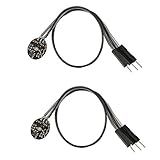
- Pulse sensor Arduino is used to test the heart rate sensor, students, artists,athletes, creator, game developer, or mobile terminal can develop interactive work related to heart rate.
- Sensors can be put on the finger or earlobe, through interconnected line can be connected to the Arduino.It also has an open source app, can real time your heart rate graph display.
- The power supply voltage: 3.3V ~ 5 v
- Package Included: 2 x Heart Rate Pulse Sensor Sensor Module For Arduino Raspberry pi
- If You Are Not Satisfied with Your Purchase for Any Reason, Please Feel Free To Contact Us at the Buyer Center or Support Email, 24/7 Quick Reply
How to build and test it in stages
- Start on a breadboard. Connect the Nano 33 BLE Sense and MAX30100 module according to their respective documentation. Keep the circuit unpowered while checking connections and supply requirements.
- Verify sensor data before adding BLE. Run the sensor library example or the project’s sensor code and inspect the output. Confirm that readings change plausibly with sensor contact; do not treat a number appearing on screen as proof that it is accurate.
- Implement beat detection and calculate values. The project initially obtained HR and SpO₂ values through a MAX30100 library, but its authors reported calm-state heart-rate readings below 40 bpm or above 150 bpm. They then described counting beats over 30 seconds and multiplying by two for HR, and using the interval between successive beats for HRV. This is the authors’ prototype approach, not a validated clinical algorithm.
- Add BLE only after local readings are inspectable. Advertise a BLE service with characteristics for the values you intend to expose. The reference project created characteristics for heart rate, temperature, HRV, and SpO₂. Use nRF Connect on a phone to find the service and inspect live values or notifications.
- Integrate charging and regulated power. Add the battery, charger, and 3.3 V regulator only after checking how each specific module connects and how the board is meant to be powered. Verify voltage and common ground before wearing the prototype. Do not charge a battery through an improvised circuit or wear exposed conductors.
- Log and inspect behavior. Capture serial CSV data and look for dropouts, implausible values, and changes associated with poor sensor contact. Compare logged output with what the BLE app displays to distinguish sensor-processing issues from a wireless-display issue.
- Make it wearable after the breadboard version works. Transfer the known-good circuit to a compact PCB, then arrange the board, battery, sensor, and strap or enclosure for skin contact and comfort. Preserve the working breadboard build while debugging the PCB: the reference authors reported that their final PCB version did not work correctly, citing time and PCB problems.
How should readings and connectivity be interpreted?
The MAX30100 uses optical sensing, so the wristband’s output depends on obtaining usable sensor contact and processing the signal correctly. A BLE characteristic can carry a computed value to a phone; it does not make that value accurate. Inspect raw or intermediate sensor behavior during development where the available library and tooling permit, and log enough data to identify when readings disappear or become implausible.
Keep the prototype’s claims narrow. The reference account describes abnormal early HR output and a changed beat-counting method, but it does not publish a clinical validation, accuracy result, tested BLE range, or measured battery runtime. It also does not provide a production cost. Do not use the wristband to diagnose a condition or make treatment decisions.
Rank #2

- TPU Stabilizer Ring included: One TPU ring helps hold the sensor against a finger for steadier contact. Signal quality can still vary with placement, finger pressure, movement, ambient light, hardware, and software.
- Analog output for maker boards: Requires a compatible development board with an analog input. Tutorials are available for selected Arduino, ESP32, Raspberry Pi Pico, and micro:bit boards; board-specific setup may be required.
- Learn, prototype, and create: Add live pulse-wave signals to classroom activities, interactive art, biofeedback experiments, and maker projects.
- Open-source hardware: Designed in New York City by World Famous Electronics LLC, made in Taiwan, and Open Source Hardware certified, US000075.
- For education and experiments: Not a medical device and not intended for diagnosis, treatment, patient monitoring, or safety-critical use.
Which Arduino-style wristband design fits a different goal?
Not every wristband needs continuous health sensing. Choose its sensor, wireless link, power strategy, feedback, and mechanical design around the job it must do.
What’s actually slowing this PC down?
Pick the symptom - the matching free tool is one click away.
| Design example | Purpose and components described | When it may fit |
|---|---|---|
| Nano 33 BLE Sense and MAX30100 | Optical HR and SpO₂-oriented prototype, BLE readings to a phone, and serial CSV logging. | When the goal is to experiment with wrist-based pulse sensing and BLE data display. |
| ESP32 timer and alert wristband | An ESP32 example combines an RTC, OLED, pushbuttons, and vibration motor for a timer; a second ESP32 and sound sensor provide Bluetooth whistle alerts. Its instructions include deep sleep for the timer. | When the main outcome is a timer or local alert rather than health measurement. |
| Temperature and proximity wristband concept | A Toronto Metropolitan University project brief proposes a development-board band with temperature and proximity sensing, two bands, Wi-Fi cloud monitoring, and a visualization back end. | When the project needs cloud-connected environmental or proximity monitoring. |
| ESP32 health-sensor capstone | A University of Houston capstone pairs an ESP32 with MCP9808 temperature and MAX30100 sensors, Arduino code, and a Blynk app; the team reports wireless HR, temperature, and blood-oxygen readings. | When a phone dashboard is preferred and an ESP32/Blynk-based example is a closer starting point. |
These examples are different design directions, not directly comparable performance tests. In particular, a Wi-Fi/cloud design has a different connectivity goal from the BLE-to-phone reference. Select a power plan deliberately: the cited examples do not provide a comparable battery-life measurement for the wristbands.
Quick Recap
Best Value

- ★Pulse Sensor is a well-designed plug-and-play heart-rate sensor for Ar-duino.
- ★The sensor clips onto a fingertip or earlobe and plugs right into Ar-duino with some jumper cables.
- ★It also includes an open-source monitoring app that graphs your pulse in real time.
- ★Power: 3-5V,Diameter: 16mm,Magnification: 330,LED Wavelength: 609nm
- ★Package Includes: 1 x Pulse Sensor Heart Rate Sensor Monitor PulseSensor for Ar-duino Module Raspberry Pi Technical support is NOT included in this auction
Rank #4

- Integrates a red LED, a infrared LED, aphotodetector, an optical equipment and a low noise electronic circuit with environmental light suppression.
- The standard I2C compatible communication interface can transmit the collected data to Arduino, KL25Z and other microcontrollers for heart rate and blood oxygen calculation.
- Apply to wearable device for heart rate and blood oxygen collection, worn on fingers, ear lobes, wrists and other places.
- The chip can also turn off the module by software, and the standby current is close to zero, so that the power supply can always be maintained.
- If you have any questions or want more information, please let us know, we will be happy to help. Your satisfaction is our priority.
Rank #3

- Package Included: 3 x Heart Rate Pulse Sensor Sensor Module Compatible with Ar-duino Raspberry pi
- The power supply voltage: 3.3V ~ 5 v
- Diameter: 16mm,Magnification: 330,LED Wavelength: 609nm
- Pulse sensor Ar-duino is used to test the heart rate sensor, students, artists,athletes, creator, game developer, or mobile terminal can develop interactive work related to heart rate.
- The sensor clips onto a fingertip or earlobe and plugs right into Ar-duino with some jumper cables.
What the reference does not establish
- Clinical accuracy or medical approval for HR, HRV, SpO₂, or temperature.
- A validated algorithm for beat detection or HRV calculation.
- Battery runtime, BLE range, or production cost.
- A guaranteed working PCB design: the authors say their final PCB did not work correctly.
- A single wiring recipe that applies to every MAX30100 breakout, charger, regulator, and battery.
Product prices and availability are accurate as of the date/time indicated and are subject to change. Any price and availability information displayed on Amazon at the time of purchase will apply.

