
The Tool Desk
Outbyte PC Repair FREEClear out junk files and repair common Windows errorsFree Scan →Outbyte Driver Updater FREEScan for outdated or missing drivers - takes under a minuteDriver Scan →iTechGuides is reader-supported. When you buy through links on our site, we may earn an affiliate commission. As an Amazon Associate I earn from qualifying purchases. Learn more
A data center has enough power for an AI workload only when its electrical service, distribution, cooling, power quality, redundancy and expansion dates can support the workload’s continuous demand and millisecond-scale peaks after the planned failure scenario. A site that advertises several megawatts can still fail if the available capacity is stranded behind a transformer, unavailable until a later energization date, unable to reject the resulting heat, or not usable after an N+1 failure.
Assess the site in this order: define the workload and growth tranches; calculate average and peak IT demand; convert IT demand to facility input with measured PUE; test rack and distribution limits; verify cooling and resilience; confirm firm utility deliverability; then prove the design with instrumented commissioning tests. Record the result in a capacity matrix that states usable continuous and peak capacity, not just a headline MW number.
1. Define the workload before asking for megawatts
Power requirements are properties of a workload configuration, not of an AI label. Record the accelerator model and count, host CPUs, memory, local storage, network fabric, management servers and any power caps. Also document whether the cluster trains models, serves inference, or does both.
Do these 3 things before closing this tab:
1Scan for outdated or missing drivers - takes under a minute2Clear out junk files and repair common Windows errors3Fix the driver behind crashes, sound loss and screen glitchesCapture operating behavior
- Utilization target: state the expected average accelerator utilization and the maximum sustained operating point. A training run can remain near its peak envelope for hours or days; an inference service may have a lower average but sharp demand changes.
- Performance objective: specify batch size and completion-time targets for training, or latency and throughput targets for inference. These determine how much headroom is acceptable.
- Ancillary load: include storage, network switches, optical equipment, orchestration, monitoring and management nodes. They draw power even when accelerators are not fully occupied.
- Criticality and recovery: state checkpoint frequency, restart time and the consequence of losing a job. A restartable batch job has a different resilience requirement from an inference service with a strict availability objective.
- Power controls: list accelerator power caps, server power-management policies and any demand-response or curtailment obligations.
Model growth as dated tranches
List each expansion tranche, its rack count and the date it must be energized. A utility connection that is adequate for the first phase may not support the second phase when it is needed. Ask the operator to identify capacity that is physically installed, capacity that is contracted, and capacity that is merely planned.
#1 Best Overall
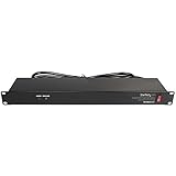
- POWER AND CHARGE: This rack mount power strip provides an additional 8 NEMA 5-15 outlets (120V/15A) and features a 6ft (1,8m) long cord so you can plug your devices in while leaving the rack mobile
- 1U RACK DESIGN: Compatible with all 19" server racks 4 inches or deeper, this horizontal-mount power distribution unit fits many network racks and has an integrated power cord; ANSI/EIA RS-310-D standard
- EASY INSTALLATION: This IT-grade rackmount PDU features a rugged steel chassis, LED indicators for ground and surge protection, and lets you control the power state with power and reset switches
- PROTECTS YOUR EQUIPMENT: This rack mountable 8-outlet (120V) power strip features a built-in circuit breaker and reset switch, ensuring a dependable performance of your networking equipment
- THE IT PRO'S CHOICE: Designed and built for IT Professionals, this rack PDU is backed for 2-Years, including free lifetime 24/5 multi-lingual technical assistance
NREL’s 2025 outlook predicts that 90% of AI workloads could be inference-based by 2030 and discusses edge deployments below 20 MW. Therefore test at least two cases: a centralized, high-utilization training cluster and a distributed inference design with many smaller sites. The latter may fit under a 20 MW edge-site pattern while imposing tighter feeder, latency and geographic constraints.
2. Build an IT power budget with both average and peak values
Start at the equipment level. Sum accelerator, host CPU, memory, storage, network, management and conversion losses. Obtain measured values from the exact server and accelerator configuration whenever possible; otherwise use a documented design maximum and mark it as an estimate.
| Budget item | What to record | Why it matters |
|---|---|---|
| Accelerators | Count, model, rated draw, power cap, sustained and transient behavior | Usually the largest and fastest-changing component of an AI rack |
| Host servers | CPU sockets, memory population, fans and motherboard draw | CPU and memory remain significant during data preparation and communication |
| Storage | Local NVMe, shared storage, controllers and expansion shelves | Training data pipelines can add continuous load beyond the GPU servers |
| Network fabric | Switches, optics, cables and fabric redundancy | High-speed links and duplicate paths add rack and room load |
| Management and conversion | Management nodes, power supplies and AC/DC conversion losses | These loads are easy to omit from an accelerator-only estimate |
Use a peak envelope, not an average
AI demand can move from 10–20% of rated power to 80–100% within 10–100 milliseconds, according to the National Laboratory of the Rockies’ 2025 analysis. Size UPS systems, switchgear, generators and controls for the fastest credible ramp, and test that ramp rather than relying on a monthly or five-minute average. A service that has enough energy over a day can still trip a breaker or overload a UPS during a synchronized job start.
Separate three IT views
- Rack IT power: the load presented by one rack, including all servers and in-rack equipment.
- Room IT power: the sum of racks, storage and network equipment in the room or data hall.
- Whole-facility IT power: all rooms and support IT before mechanical and building overhead.
Keep continuous, design-peak and short-duration transient values in each view. State whether a value is per rack, per row, per room or for the entire campus so that numbers are not accidentally added twice.
3. Convert IT power into facility power
Use the relationship:
Facility power (MW) ≈ IT power (MW) × PUE
PUE is the ratio of total facility input to IT equipment power. Use a measured PUE from comparable operating conditions when available, and document the outside temperature, cooling mode, IT utilization and measurement boundary. A design PUE is not a guarantee at a different load or climate.
Include every overhead
- Chillers, cooling towers, pumps, fans and heat-rejection equipment
- UPS and power-distribution losses
- Transformers, switchgear and power-conversion equipment
- Lighting, controls, fire systems and building services
- Support spaces and non-IT loads that share the electrical service
For example, an illustrative 20-rack cluster averaging 40 kW of IT power per rack uses 0.8 MW of IT power. At an illustrative PUE of 1.30, the facility input would be approximately 1.04 MW. This arithmetic is a planning example, not a performance claim for any particular site; replace both inputs with the site’s measured values.
Rank #2

- RACK MOUNTABLE: This 1U Rackmount PDU power strip fits 19" standard server racks and cabinets, featuring a 1U horizontal rack mount form factor that ensures compatibility with all 19" server racks.
- 15A Overload Protection Switch: Provides overload protection by interrupting the circuit when the load exceeds the rated current.
- HEAVY-DUTY: The power distribution unit features a heavy-duty construction, meticulously designed with robust components and housed in a durable aluminum alloy casing, ensuring a sturdy and long-lasting performance for reliable power management.
- POWER CORD: The power distribution unit comes equipped with a 6-foot (1.8 meter) 14AWG power cord, providing flexible placement options and extended reach for versatile installation in various settings.
- Commitment: ElecVoztile is dedicated to delivering superior products and outstanding customer service. Should you encounter any issues, please do not hesitate to reach out to us for immediate assistance.
Calculate usable redundant capacity
Usable redundant capacity is the load that remains supportable after the defined utility-feed, UPS, generator or distribution failure while still meeting thermal and power-quality limits. Do not count a redundant component if operating it at the required load would exceed its rating, derating curve or cooling capability. Express the result as usable MW and kW per rack after the failure, not as nameplate capacity before it.
4. Verify rack density and electrical distribution
Map each calculated rack load through the complete path: busway or overhead bus, rack power-distribution unit (rPDU), branch breaker, panel, transformer, UPS, switchgear and generator. The smallest limit or the applicable derating rule governs.
Check the rack and row envelope
- Compare continuous and peak rack kW with the busway and rPDU ratings.
- Apply breaker, conductor, ambient-temperature and altitude derating.
- Confirm the number of supported systems per rack and the resulting stranded capacity at peak demand.
- Verify that independent A and B feeds are actually routed through separate protective and conversion equipment.
- Check floor loading, cable space and the ability to add racks without violating airflow or service clearances.
NVIDIA’s DGX H100 data-center design guidance specifies circuit capacity, breaker derating, supported systems per rack and stranded capacity at peak demand. Its preferred high-density pattern is 415 VAC, 32 A, three-phase with N+1 redundancy. Treat those values as requirements for the referenced DGX configuration, not as universal values for every accelerator platform; obtain the exact electrical schedule for the systems you will install.
Uptime Institute reported in 2026 that rack densities above 30 kW are becoming more common and that densities above 50 kW are increasingly seen in AI environments. Those figures are market context, not permission to assume that a candidate hall can carry such a rack. Require a site-specific, measured or engineered limit for your rack design.
Inspect power quality
Ask for allowable voltage and frequency ranges, harmonic limits, phase balance, transfer-time specifications and protection-coordination studies. Verify that the UPS can regulate the rapid load ramps described above without nuisance transfer or overload. A nominally adequate MW supply that produces voltage sags, harmonics or uncoordinated breaker trips is not adequate for a multi-node job.
Recommended Free Tools
5. Match cooling capacity to the electrical design
Every watt delivered to IT eventually becomes heat. The cooling plant must reject the facility’s actual thermal load at the expected outdoor conditions, while pumps, fans and controls remain within their own electrical budget.
Rank #3
- 100-125V/15A Basic Power Distribution Unit (PDU) delivers AC power to data centers, network closets, and other electrically demanding applications
- OUTPUT: 10 Rear NEMA 5-15R Outlets; INPUT: NEMA 5-15P straight plug with 15 ft power cord
- VERSATILE RACKMOUNT OPTIONS: Allows for the PDU to be installed vertically or horizontally
- ADDITIONAL FEATURES: Network-grade plugs and outlets, durable metal housing, and cord retention tray
- 3-YEAR LIMITED WARRANTY (This unit does not provide surge suppression)
Validate the thermal path
- Confirm supply and return air or coolant temperatures at the rack inlet and outlet.
- Measure coolant flow, heat-exchanger approach temperature and control response where liquid cooling is used.
- Check chiller, cooling-tower, dry-cooler and pump capacity at design-day conditions, not only at a favorable test temperature.
- Verify water availability, treatment, leak detection and isolation procedures.
- Test airflow containment and blanking panels for any air-cooled portion of the rack.
Uptime identifies direct-to-chip cooling, rear-door heat exchangers and immersion systems as production-scale options as rack densities rise. NVIDIA’s GPU-ready guidance treats power and cooling together with rack layout, storage and network architecture. Select the cooling technology from the rack’s sustained and transient heat load; adding electrical capacity without heat-rejection capacity only moves the bottleneck.
6. Prove resilience and failure behavior
Define the failure scenario that the service-level objective requires: loss of one UPS module, one utility feeder, one generator, one transformer, one rPDU feed or an entire maintenance path. Then calculate the surviving electrical and cooling capacity under that exact event.
Use independent paths
- Provide dual utility or UPS paths where the workload requires them, with genuinely independent upstream equipment.
- Use independent A and B rPDU feeds and verify that server power supplies are connected as designed.
- Confirm generator fuel autonomy, refueling arrangements and starting sequence.
- Document maintenance topology so planned work does not consume the same margin as an unplanned failure.
- Match ride-through time to the generator-start and transfer sequence, including controls and networking.
Facility-level UPS and generator backup are required in NVIDIA’s DGX SuperPOD design guidance. It warns that failure of one system in a multi-node AI workload can stop the entire job on all systems. For workloads that cannot recover from a checkpoint, the guidance specifies at least three power sources to each rack. If your application can checkpoint and restart, quantify the restart time and data loss instead of assuming that checkpointing eliminates the need for electrical redundancy.
7. Confirm that the utility can actually deliver the power
Request evidence for the service, not a marketing capacity figure. The utility and site operator should provide:
- Firm contracted service level and point-of-interconnection voltage
- Completed utility and interconnection studies
- Substation and feeder headroom under normal and contingency conditions
- Committed energization date for each expansion tranche
- Curtailment, interruptibility and demand-response terms
- Recent outage history and restoration performance
- Generator-fuel, emissions and operating constraints that affect backup capacity
Separate installed equipment from deliverable service. A transformer may be physically present but constrained by the upstream feeder, protection settings or the utility’s contract. DOE describes resource adequacy as a forward-looking comparison of supply, demand and generation development, and notes that data-center growth is placing significant burdens on the grid.
In a 2025 DOE reliability analysis, 154 GW was in advanced development but only 19 GW was able to operate around the clock under the analysis assumptions. The comparison illustrates why announced or developing generation is not equivalent to firm, dispatchable capacity at your interconnection. Require a date-certain energization plan and identify what happens if that date slips.
Rank #4

- 10 NEMA 5-15R Outlets with Long Power Cord: This rack mount power strip provides 10 NEMA 5-15 outlets (15A) and features a 6ft long cord to conveniently plug in devices, keeping the mounting more easily and flexible
- Universal 19-Inch Rack Compatibility: Compatible with all 19-inch server racks 4 inches or deeper, this horizontal-mount power distribution unit fits many network racks and has an integrated 6ft/1.8m power cord
- Fireproof Heavy-Duty Construction: This server rack mountable power distribution unit features whole housing fireproofed construction that will support long-life working performance
- Built-In Circuit Breaker Protection: This rack mountable 10-outlet (AC100-240V) power strip features a built-in circuit breaker and reset switch, ensuring dependable performance of your power equipment and safety for using power
- Industrial-Grade Materials and Design: Features industrial equipment pure copper wire material for high power capacity, industrial-grade metal housing, and cord retention tray for enhanced durability
8. Commission with measurements and staged tests
Paper calculations should be followed by instrumented tests on representative racks and every upstream electrical path that will carry the production load.
Quick wins for a faster PC:
Fix the driver behind crashes, sound loss and screen glitchesFind Drivers →Repair Windows errors before they cause bigger problemsFix Now →- Instrument the system: install calibrated three-phase power analyzers at rack, row, UPS output, switchgear and utility-interconnection boundaries.
- Establish a baseline: record voltage, current, frequency, harmonics, temperatures, coolant flow and PUE at steady state.
- Apply a step load: reproduce the expected accelerator ramp, including a transition from 10–20% toward 80–100% of rated power within 10–100 milliseconds where equipment permits.
- Test startup and transfer: verify simultaneous server starts, UPS transfer, generator start, retransfer and controls without nuisance trips.
- Test failure cases: remove each defined redundant component in turn and confirm surviving electrical and cooling capacity.
- Run a sustained workload: operate representative training and inference patterns long enough to expose thermal drift, pump limits and fuel or water constraints.
- Close the record: capture alarms, protection coordination, temperatures, recovery times and corrective actions in signed test reports.
The deliverable should be a signed capacity matrix with continuous kW, peak kW, usable MW after each required failure, maximum supported rack kW, cooling limit, utility limit and the date each tranche is genuinely available.
9. Compare candidate sites on the limits that matter
| Comparison axis | Evidence to request | Pass question |
|---|---|---|
| Firm deliverable MW and energization date | Utility contract, study, feeder data and tranche schedule | Will the required MW be energized before each workload milestone? |
| Rack kW and cooling technology | Rack electrical schedule, busway/rPDU ratings and thermal design | Can the exact rack run continuously and through its peak without thermal violation? |
| Usable capacity after failure | N+1 or other contingency calculations and test results | Does the surviving path support the workload, not merely the empty facility? |
| Power quality and transient response | UPS specifications, waveform records and step-load tests | Are voltage, frequency, harmonics and transfer response within equipment limits? |
| PUE and utilization | Measured PUE with operating conditions and boundary defined | Is the facility estimate based on comparable load and climate conditions? |
| Expansion and outage risk | Substation plan, outage history, maintenance procedures and curtailment terms | Can growth proceed without consuming required resilience margin? |
A site passes only when every axis satisfies the workload’s service-level and growth requirements. The weakest axis is the capacity constraint, even if the other five look favorable.
10. Worked screening example
Consider an illustrative first tranche of 20 racks, each designed for 40 kW of continuous IT load. The IT total is 0.8 MW. Applying an illustrative PUE of 1.30 gives approximately 1.04 MW of facility input. The screening is incomplete until you answer four additional questions:
- Can each rack’s busway, rPDU, breaker, transformer and UPS path carry 40 kW continuously and the specified transient?
- After the required UPS, feeder or generator failure, is at least the workload’s required load still available?
- Can the cooling plant reject 0.8 MW of IT heat plus its operating margin at design-day conditions?
- Is 1.04 MW firm and energized by the tranche date, or is it only a future utility reservation?
If any answer is unknown, the site is not yet proven adequate. Replace the illustrative rack load, PUE and tranche date with measured or contractually documented values before approving deployment.
What’s actually slowing this PC down?
Pick the symptom - the matching free tool is one click away.
11. Common assessment mistakes
- Using the utility nameplate as usable AI capacity: subtract redundancy, derating, cooling and other committed loads.
- Multiplying only the accelerator count by a rated wattage: add hosts, memory, storage, networking, management and conversion losses.
- Planning from averages: include fast step loads and synchronized job starts.
- Assuming a low PUE transfers between sites: require the measurement boundary and operating conditions.
- Ignoring stranded capacity: a breaker or voltage configuration can leave installed MW unusable at the rack.
- Treating a single A/B pair as independent without tracing it: verify separate upstream paths and protection.
- Counting planned generation as firm supply: distinguish advanced development from round-the-clock deliverability.
- Adding power without adding heat rejection: size electrical and cooling systems as one design.
- Skipping failure tests: calculations do not reveal control interactions, nuisance trips or thermal drift.
12. The final pass/fail rule
Approve the facility only when the workload’s continuous and transient demand, rack density, cooling rejection, redundancy requirement, power quality and utility deliverability all remain within documented limits, with the required headroom and energization dates. Keep the signed capacity matrix under change control: any accelerator refresh, power-cap change, new inference service, cooling-mode change or utility revision can invalidate the previous assessment.
Quick Recap
Product prices and availability are accurate as of the date/time indicated and are subject to change. Any price and availability information displayed on Amazon at the time of purchase will apply.

