
iTechGuides is reader-supported. When you buy through links on our site, we may earn an affiliate commission. As an Amazon Associate I earn from qualifying purchases. Learn more
A divide-and-conquer e-fuse architecture separates circuit protection into two independent electronic roles and a mechanical last resort. In the example described by Electronic Design, a fast primary controller handles short circuits, overcurrent and temperature, while a diverse reactive supervisor watches for permanent failures and commands a disconnect. A silicon-carbide (SiC) switching stage interrupts current quickly; a mechanical air gap then provides galvanic isolation when electronic protection cannot be trusted.
This arrangement addresses a central problem in high-voltage DC systems: faults can develop faster than a system-level safety controller can react, yet relying on one controller creates a single point of failure. The article presents the architecture as a design pattern for automotive zonal power, DC microgrids, energy storage, industrial DC backbones, data centers, bidirectional chargers and battery backup systems—not as a certified product or proof that any specific implementation meets a safety integrity level.
What the divide-and-conquer e-fuse design does
The architecture divides circuit-protection work by timing and purpose. A primary subsystem performs the normal, application-aware protection functions. It measures current and temperature, identifies a short circuit or overload, and drives the power switch that interrupts current. A second subsystem is intentionally different: it continuously checks whether the primary subsystem is behaving plausibly and can force the circuit into a safe state if the primary has failed in a way that leaves it permanently on.
The final layer is a mechanical disconnect. Electronic switches are small and fast, but a failed semiconductor can remain conductive. Opening a physical air gap supplies galvanic isolation even when the electronic path or its gate driver is no longer reliable. The result is not redundancy in which two identical controllers perform the same calculation; it is a primary function, an independent reaction function and a physical isolation function.
#1 Best Overall

- DIN Rail Mount Power Distribution Fuse Module Board.
- Work voltage: AC or DC 5~32V, total current rating 40Amp. PCB Dimensions: 150mm x 72.5mm x 29mm (W x L x H). Module Dimensions: 153mm x 87mm x 53mm (W x L x H).
- Input terminals: pitch - 7.62mm/0.3", current 30A for per position, wire size 26~10 AWG, stripping length 8mm, Metric M3 slotted screw.
- P1 output terminals: pitch - 5.08mm/0.2", maximum current 10A for per position, wire size 26~12 AWG, stripping length 7mm, Metric M2.5 slotted screw.
- P2-1 to P2-10 output terminals: pitch - 7.5mm/0.295", maximum current 10A for per position, wire size 26~12 AWG, stripping length 7mm, Metric M2.5 slotted screw.
The source for this architecture is the September 2, 2026 Electronic Design article on a divide-and-conquer e-fuse. Its timing and voltage figures are article-reported design claims, not universal limits or independently verified measurements.
Why conventional protection becomes difficult at high DC voltage
Traditional protection remains useful, but modern distribution systems impose competing requirements:
- Speed: A short circuit can develop in roughly 100 ns, according to the article. The power switch and its sensing path therefore need a response measured in microseconds, not only the tens of milliseconds often available to a complete system.
- Reset and recovery: A conventional fuse is effective but generally single-use. A resettable electronic switch can support controlled recovery, diagnostics and selective restart, provided the fault has cleared and the switch itself is healthy.
- Size and integration: Contactors and other mechanical interrupters provide a clear physical gap but are slower and physically larger than a semiconductor stage. Electronic protection can be integrated close to loads and controlled over a vehicle or facility network.
- Failure behavior: A controller, sensor, gate driver or power transistor can fail in a way that defeats the protection command. A separate monitor and a mechanical disconnect address that failure mode rather than assuming the main controller is always available.
- Higher bus voltage: The article notes data-center power-density trends pushing busbar voltages toward 800 V DC. At that voltage, arcing, insulation coordination, stored energy and safe service isolation become system-level concerns, not merely software decisions.
These are trade-offs, not a claim that one topology replaces every fuse, breaker or contactor. The suitable choice depends on fault energy, allowable interruption time, isolation requirements, environmental conditions and the applicable safety case.
The Tool Desk
Outbyte Driver Updater FREEFix the driver behind crashes, sound loss and screen glitchesFind Drivers →Outbyte PC Repair FREERepair Windows errors before they cause bigger problemsFix Now →Three ways to make a protection function fail-safe
Inherent fail-safety
An inherently fail-safe design uses a component’s physical behavior to move toward safety when it fails. A normally open element that loses power and opens is a simple example. This approach can be elegant, but it cannot cover every fault, especially a semiconductor that fails short or a welded contact.
Composite fail-safety
Composite fail-safety distributes the same or closely related safety function across multiple independent subsystems. Channels may cross-check one another, and a disagreement can trigger a safe state. Independence, diagnostic coverage and the treatment of latent faults determine how much protection the duplication actually provides.
Reactive fail-safety
Reactive fail-safety gives the primary subsystem responsibility for the normal function and assigns a secondary subsystem a different monitoring and negation role. The monitor does not need to reproduce every primary algorithm. It can use indirect measurements, plausibility checks, averaging or time-integrated metrics, then issue a disconnect command when behavior indicates a permanent failure. The monitor must still act within the process safety time—the interval in which a fault can be controlled before unacceptable damage occurs.
Rank #2

- Simple to install, simple to use
- Makes adding or removing aftermarket electrical devices/electronics to your CAN/Bus-equipped vehicle a breeze
- Built with components selected for superior power management capability and extended service life
- Offers six power circuits to handle your favorite gadgets and accessories
The e-fuse example combines composite independence with reactive behavior: the primary controller protects the load during normal operation, while the supervisor watches for evidence that the primary has become unsafe.
PC Slower Than It Used to Be?
A free scan shows the junk files, broken settings and background clutter dragging Windows down - then fixes them in one click.Free scan · Windows 10 & 11Crashes, No Sound, or Screen Glitches?
Random freezes, missing sound and display glitches usually trace back to one bad driver. Find and replace yours safely.Free scan · under a minuteInside the bidirectional e-fuse architecture
Primary real-time controller
The article identifies a Microchip dsPIC33A digital signal controller (DSC) as the example application controller. In this role it processes the current and temperature signals, applies the application’s overcurrent and short-circuit rules, manages overtemperature protection and controls the SiC switching module through a multistage gate-driver path. It can also coordinate diagnostics, communication and a controlled reset after a transient.
Reactive supervisor
An AVR SD controller is shown as the independent reactive monitor. It continuously observes indications from the main system and checks whether they are plausible. If the primary path is stuck on, has stopped executing, or is reporting a state inconsistent with measured current or temperature, the supervisor can assert a fault and command the disconnect. Its job is deliberately narrower and different from the primary control loop, which helps avoid sharing the same software and hardware failure modes.
Fast electronic interruption
The SiC module is the high-speed current-interruption element. SiC devices can be switched rapidly and can be arranged for bidirectional current blocking, allowing the e-fuse to protect a power path that may carry current in either direction. The article assigns short-circuit handling, overcurrent protection and overtemperature management to this solid-state stage. A current preprocessor and a Hall-effect isolated current sensor or bidirectional shunt feed the measurement chain, depending on the application.
Mechanical isolation
An air-gap disconnect and its driver provide the last-resort path to a safe, de-energized state. The electronic switch can stop current first, reducing stress on the mechanical contacts; the mechanical element then opens to establish galvanic isolation for service, a persistent fault or a failed semiconductor. The roles are complementary: fast interruption limits energy, while the air gap supplies a visible and electrically robust separation.
Recommended Free Tools
Isolation and fault signaling
Galvanic isolation between the primary and reactive subsystems reduces the chance that one supply, ground fault or transient defeats both channels. The block-level design includes an isolated DC-DC converter and transformer, dual-port isolators, OR logic for fault indications, power monitoring and regulation, a push-pull driver and a disconnect driver. Isolation is a risk-reduction measure, not proof that common-cause failure has been eliminated; layout, power distribution, firmware, sensors and the mechanical assembly still require analysis.
Rank #3
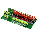
- Panel Mount Power Distribution Fuse Module Board.
- Work voltage: AC or DC 5~32V, total current rating 40Amp. Dimensions: 150mm x 72.5mm x 29mm (W x L x H).
- Input terminals: pitch - 7.62mm/0.3", current 30A for per position, wire size 26~10 AWG, stripping length 8mm, Metric M3 slotted screw.
- P1 output terminals: pitch - 5.08mm/0.2", maximum current 10A for per position, wire size 26~12 AWG, stripping length 7mm, Metric M2.5 slotted screw.
- P2-1 to P2-10 output terminals: pitch - 7.5mm/0.295", maximum current 10A for per position, wire size 26~12 AWG, stripping length 7mm, Metric M2.5 slotted screw.
Reusable and application-specific building blocks
The article separates general-purpose infrastructure from elements that must be tailored to the installation.
| Reusable block | Purpose in the architecture |
|---|---|
| dsPIC33A DSC | Real-time application control, protection decisions and switching commands. |
| AVR SD controller | Independent reactive supervision and forced-safe-state command. |
| Push-pull and multistage gate drivers | Translate controller outputs into the current and voltage needed by the SiC switching stage. |
| Isolated DC-DC converter, transformer and dual-port isolators | Maintain electrical separation between control domains and the power stage. |
| OR fault logic, power monitoring and regulation | Combine fault indications and keep both controllers within their operating limits. |
| Air-gap disconnect and disconnect driver | Provide mechanical galvanic isolation after an electronic trip or a detected permanent fault. |
| Application-specific element | Why it must be engineered for the system |
|---|---|
| Hall-effect isolated current sensor | Its range, bandwidth, isolation rating and placement must match the bus current and fault waveform. |
| Module-temperature monitor | Thresholds depend on the SiC module, heatsink, cooling system and allowable junction temperature. |
| Bidirectional shunt | Requires a suitable resistance, power rating, Kelvin layout and bidirectional signal conditioning. |
| Leakage-detection circuit | Must detect insulation or ground faults without nuisance trips from normal common-mode behavior. |
| SiC module and current preprocessor | Voltage, current, switching energy, short-circuit withstand and measurement bandwidth are installation-specific. |
Possible host interfaces listed in the article include LIN, CAN, 100BASE-T1S single-pair Ethernet and standard Ethernet. The interface choice affects diagnostics and integration, but it should not be the sole path for a time-critical trip; the local protection and supervisor need deterministic behavior if the network is delayed or unavailable.
How the protection sequence works
- Measure the power path. The current sensor, shunt, leakage detector and temperature monitor provide signals to the primary controller and selected independent monitor inputs. Define sensor ranges, sampling rates, isolation barriers and diagnostic coverage before selecting thresholds.
- Detect and classify the event. The primary controller distinguishes a fast short circuit from an overload, thermal problem or communication fault. The article’s example places short-circuit detection and mitigation in a window of about 2 µs, while noting that a short can develop in roughly 100 ns. Those figures describe the article’s design discussion, not a guaranteed response for every implementation.
- Interrupt electronically. The primary path commands the SiC stage off through the gate driver. Bidirectional arrangements must block the relevant current direction and manage reverse conduction, gate timing and energy in the commutation path.
- Supervise independently. The reactive controller compares indirect measurements and fault indications with expected behavior. It can use plausibility checks, averaging or time-integrated metrics so that a brief, recoverable transient is not treated identically to a controller that is permanently stuck on.
- Force a safe state when needed. If the monitor detects a permanent primary failure or an unsafe discrepancy, isolated fault logic drives the disconnect. The mechanical air gap then provides galvanic isolation even if the semiconductor path cannot be trusted.
- Report, diagnose and recover. Once the energy is controlled, the system can record the cause, verify that bus voltage has decayed, check insulation and temperature, and decide whether an automatic reset is permitted. A persistent or safety-critical fault should require a service procedure rather than repeated automatic retries.
The article says a safety e-fuse may have 10 ms to respond at the system level, while the subsystem that detects and mitigates a short may need to react in about 2 µs to avoid permanent damage. A real design must allocate those budgets across sensing, computation, isolation, gate drive, semiconductor turn-off, contactor motion and energy discharge.
Composite versus reactive architectures
| Design question | Composite arrangement | Reactive arrangement |
|---|---|---|
| What do the channels do? | Multiple subsystems execute the same or closely related safety function and cross-check results. | A primary subsystem performs the function; an independent supervisor monitors and negates it when necessary. |
| Response to disagreement | A discrepancy can trigger transition to a safe state. | The supervisor issues a forced-safe command when behavior violates its independent checks. |
| Timing model | Often requires both channels to calculate and compare within the protection window. | Can tolerate some monitoring latency if action occurs within process safety time. |
| Fault coverage | Strong for disagreements detectable by cross-checking; latent common faults remain a concern. | Strong for permanent primary failures that produce observable symptoms; undetectable shared faults remain a concern. |
| Complexity | More duplicated computation and comparison logic. | Different algorithms and hardware can simplify the monitor but require careful definition of plausibility rules. |
| Common-cause risk | Reduced by independence and diversity, but not automatically removed. | Reduced when the supervisor uses different technology, power and development paths and is galvanically isolated. |
Neither pattern is inherently sufficient by itself. The useful question is whether the proposed independence is real: separate power domains, sensors where practical, firmware and tools, physical routing, clocks, reset sources and failure assumptions should be examined rather than counted as separate merely because two processor part numbers are different.
Mechanical versus electronic interruption
| Characteristic | Electronic SiC interruption | Mechanical air-gap disconnect |
|---|---|---|
| Response | Designed for microsecond-scale control in the article’s example. | Contact motion is slower and must be included in the system energy and safety budget. |
| Isolation | Off-state blocking is not the same as a physical service gap. | Provides galvanic isolation when open. |
| Size and integration | Compact and suitable for distributed, digitally controlled protection. | Physically larger, with mechanical mounting and actuator requirements. |
| Recovery | Can support diagnostics and controlled reset if the fault is transient. | May require a deliberate reclose sequence or service intervention. |
| Failure concern | A semiconductor can fail short or a gate driver can fail. | Contacts can weld, wear or fail to move; position feedback is therefore important. |
The divide-and-conquer approach uses each technology where it is strongest instead of asking one device to provide both instantaneous current limiting and verified isolation.
Independent reader supportYour contribution helps us test, update, and keep practical guides available for everyone.Applying the pattern to a real system
Set the safety and energy requirements first
Define the maximum bus voltage, normal and fault current, stored energy, allowable touch voltage, process safety time, isolation voltage, environmental range and required service state. For an 800 V-class bus, creepage, clearance, insulation monitoring, arc management and discharge time need explicit calculations. Do not infer a rating from the article’s “toward 800 V DC” statement; it is a trend description, not a component specification.
Rank #4

- Switch Power Socket Module: 3 Pin power socket inlet module with on-off button. Voltage: 125/250V AC. Built-in 10A fuse to protect the device from over voltage, over loading and short circuit. The design of LED indicator light makes the item safe, secure and efficient to use.
- Upgrade Version: Our power switch socket is the new version providing more convenient and neater wiring. Coming with 3 pcs colored wires for quick wiring, yellow wire connects to G (ground), red wire connects to L (fire) and blue wire connects to N (zero). Also, the wiring harness with U-type plug makes the installation easier and painless.
- Easy Installation and operation: The power socket switch is installed well in a complete set and can be used directly. Note: For electrical maintenance and installation, be sure to take necessary power-off and insulation protection measures.
- Wide Range of Application: Widely used for 3D Printers, Computer, home appliance, office equipment, fitness equipment, rice cookers and other equipment with the same interface.
- Package Includes: 2 x Rocker Switch Power Socket Inlet Module Plug with wires, 2 x 10A Fuse, 2 x 15A Fuse, 4 x mounting screws.
Allocate independent responsibilities
Write a fault matrix that names the primary action, the independent observation, the reaction time and the final actuator for each short circuit, overload, overtemperature, sensor failure, controller lockup, gate-driver fault, welded contact and loss-of-power case. Keep the monitor’s checks simple enough to verify and different enough to avoid reproducing the primary failure.
Engineer isolation and diagnostics
Separate supplies and communication paths where the safety analysis requires it. Add feedback for SiC gate status, disconnect position, bus voltage decay and sensor plausibility. Test single faults, power interruptions, stuck-at signals, corrupted messages, thermal drift and loss of the monitor itself. A supervisor that cannot detect its own failed output is not an independent safety barrier.
Validate switching and mechanical behavior together
Measure turn-off overshoot, parasitic inductance, short-circuit energy, gate-driver desaturation behavior, electromagnetic interference and contact opening under the worst expected current. Confirm that the mechanical disconnect opens only after the electronic stage has reduced current when that sequencing is required, and verify that residual bus energy is discharged before service access.
Standards, independence and certification limits
The article discusses IEC 61508 synthesis, ISO 26262 decomposition and EN 50129 architectural approaches. It points to functional diversity, technology diversity and independent development processes or tools as ways to support subsystem independence. Those concepts can guide a safety case, but the article is not the standards text, a certification report or a complete hazard analysis.
Do not claim that the example automatically achieves a Safety Integrity Level (SIL) or Automotive Safety Integrity Level (ASIL). The actual result depends on the target standard edition, operating environment, hardware metrics, diagnostic coverage, systematic-capability evidence, independence argument, verification records and assessor review. A product team must map requirements to the applicable standard and document tests and failure analyses for its own implementation.
Where the architecture may fit—and where it may not
The authors identify automotive zonal distribution, DC microgrids, energy-storage systems, industrial DC backbones, data-center distribution, bidirectional charging and battery backup as possible applications. These systems share a need for fast interruption and controlled recovery, but their fault currents, isolation rules, service procedures and communications differ substantially.
A category-level bidirectional e-fuse module should not be assumed suitable for this architecture. Before considering any commercial assembly, verify its continuous and peak voltage and current, bidirectional operation, short-circuit withstand, response time, isolation rating, thermal design, fault latching behavior, mechanical disconnect capability and intended application. The source article does not specify a retail model, price, rating or listing, so those details cannot be inferred.
Quick Recap
Key design takeaways
- Use a fast primary protection loop for application-level decisions and a diverse reactive supervisor for permanent-failure detection.
- Combine SiC electronic interruption with a mechanical air gap when galvanic isolation and service safety matter.
- Allocate the timing budget explicitly: the article cites roughly 100 ns fault development, about 2 µs subsystem mitigation and a possible 10 ms system-level allowance.
- Treat galvanic isolation, diverse technology and independent development as engineering requirements to verify, not labels to assume.
- Use the architecture as a starting point for a documented safety case; it is not, by itself, evidence of SIL, ASIL or certification.
Product prices and availability are accurate as of the date/time indicated and are subject to change. Any price and availability information displayed on Amazon at the time of purchase will apply.

