
What’s actually slowing this PC down?
Pick the symptom - the matching free tool is one click away.
iTechGuides is reader-supported. When you buy through links on our site, we may earn an affiliate commission. As an Amazon Associate I earn from qualifying purchases. Learn more
Your feed-rate calculation estimates the time spent cutting a defined distance; it does not automatically include the full machine cycle. Rapid positioning, tool changes, preparation and completion actions, and control or configuration settings can all add elapsed time. To diagnose the difference, first make sure you are comparing the same interval and the same kind of timer.
What the machining-time calculation actually measures
For a milling cut, Haas’s Machinist’s CNC Reference Guide gives the time for cutting a distance as:


- Minutes: TCm = L ÷ IPM
- Seconds: TCs = L ÷ IPM × 60
L is the cutting distance, and IPM is feed in inches per minute. In metric work, use consistent metric units for distance and feed. This calculation estimates a cutting segment; it is not, by itself, a prediction of the full program or production cycle.
Finding the feed rate for a milling estimate
The same guide gives IPM = FPT × T × RPM, where FPT is feed per tooth, T is the number of cutter teeth, and RPM is spindle speed. Use the feed rate appropriate to the operation and actual programmed conditions. Haas advises checking actual cutting conditions against the tooling manufacturer’s recommendations in its milling cutter troubleshooting guide.
#1 Best Overall
Do not use the milling formula for every operation
The guide also provides a lathe-time calculation based on feed per revolution and RPM. The milling formula above is not a universal formula for every CNC operation; choose the relationship that fits the process and units.
What adds time beyond cutting
A CNC program contains preparation, cutting, and completion activity. Haas describes preparation as including actions such as selecting work and tool offsets, selecting a tool, turning on coolant, setting spindle speed, and choosing positioning mode. The cutting portion defines the tool path and feed rate. The program’s remaining completion activity also belongs to the full program interval, even though it is not part of the distance/feed calculation. See Haas’s SR programming documentation.
Rank #2
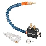
- PACKAGE : A Coolant Mister +Magnet Base+4x2.5mm Hose(1.5m/5ft) Air In 1/4 Inch,Oil In Pipe 4mm(5/32")
- HIGH EFFICIENCY : Cooling, Lubricating and Chip Blowing can be Completed at One Time During Processing, Increasing the Machining Cutting Speed, Save Time and Reduce Processing Costs and Tool Wear
- APPLICATION : The Mist Coolant Lubrication Spray System Is Suitable for Lubricat of Metal Lathes Mill, Milling Machine, Grinding, Tapping, Router Machining Centers, Sawing Machines, Woodworking Equipment, Feeders and other Equipment Cool Mist on Engraving Tools and Accessories
- SAVE COOLING LIQUID : The cnc Mist Coolant System can Save the Cooling Liquid, can Control the Capacity of the Sprayer and Coolant, Save Air Tool Oil,Anchor Lube
- LONG SERVICE TIME:In the Liquid without Pressure Output Required to Ensure that the Air Pressure in the Range 5-7kgf / cm2 (Atomization and Gas, Associated Gas Pressure)
Rapid positioning and other non-cutting moves
Moves that do not cut material still consume elapsed time. Haas’s 2024 Lathe Operator’s Manual identifies G00 moves, home moves, tool-change moves, and non-machining canned-cycle motions as rapid motions. A feed-rate estimate based only on cutting distance does not count these moves.
Tool changes and machine-specific performance
Tool-change time and rapid performance depend on the machine and its configuration. As one bounded example, Haas lists a DT-I performance package with rapid speed changing from 1,880 to 2,400 inches per minute and chip-to-chip tool-change time changing from 2.4 to 1.8 seconds on its DT-1 product page. These are specifications for that Haas machine and option, not typical or guaranteed values for other CNC equipment.
Rank #3

- 【CNC Z Axis Setter】This is a high precise hardware tool for correcting and setting Z axis of CNC machine tool, sensitive and precise. Z Axis Setter Reading Resolution is: 0.01mm/0.0005"; Repeatability: 0.01mm/0.0005"; Body height: 50.8mm/2"; Response speed: 1m/s.
- 【High Accuracy】Compared with traditional tool setting methods, the z axis zero setter has a mechanical dial with stable performance. It has two dials, the large one is the scale and the small one represents the cycles. The accuracy can reach 0.0005 inches and it is easy to read. It can reduce manual error and ensure the consistency of measurement results.
- 【Magnetic Design】The Z Axis Setter has 4 strong magnets embedded in the bottom, easy to fix and non-slip, and can be used horizontally or sideways. The measuring surface of the cnc tool setter is spring-loaded with low elasticity. It can protect the tool and effectively prevent it from being damaged or broken.
- 【With Storage Case】The z axis zero setter is equipped with a shock-resistant storage case, which makes it easy to store and move the machine. It can prevent damage to the machine and avoid inaccuracies.
- 【Wide Application】The cnc gauge setter can be used to measure and correct the height of the z-axis. It is not limited by the material of the workpiece, which makes it highly applicable. Suitable for CNC Lathe,Milling Machine,Drilling Machine.
Safe Run and prove-out settings
For supported Haas controls, Safe Run is another configuration to check when a first run or prove-out takes longer. The 2024 Haas Lathe Operator’s Manual says Safe Run increases cycle time significantly and does not recommend running a reliable program with it. That warning is specific to the documented Haas feature; check the manual for the machine and control in use.
Compare the same timer and the same interval
A displayed time is meaningful only when you know what it counts. Haas control documentation distinguishes feed time from broader total time or total tool-use time, and some controls display tool usage or tool-change counts. The available labels and definitions vary by model and configuration, so consult the manual for the exact control rather than assuming one counter represents a universal part-cycle definition. Relevant Haas documentation includes the Next Generation Control Operator’s Manual and Mill Operator’s Manual operation section.
Rank #4
For a useful estimate-to-machine comparison, align the start and stop points, tool sequence, and treatment of setup, loading, and operator actions. If the calculated value covers only cutting but the machine timer covers a broader interval, the two figures answer different questions.
A practical way to find the source of the gap
- Write down the estimate’s scope. Record the cutting distance, feed rate, units, and whether the estimate covers one cut or the whole program.
- Identify the machine timer. Check the control manual to learn whether the displayed value is feed time, tool-use time, or another total, and what events start and stop it.
- Match the measurement interval. Use the same program start and end points for both figures. Decide explicitly whether setup, loading, and operator actions count.
- Account for non-cutting program activity. Review rapid moves, home and tool-change moves, canned-cycle motions, and preparation or completion actions that fall inside the measured interval.
- Check configuration and machine-specific specifications. Confirm whether Safe Run or another relevant mode is active, and use rapid and tool-change figures only when they apply to the machine and option being evaluated.
- Revisit the cutting inputs. Verify that the feed rate and cutting distance represent the operation as programmed, using the correct formula for milling or turning.
When comparing two cycle-time estimates or machines
Compare like with like rather than treating a single feed-rate figure as a complete machine comparison. Useful dimensions include:
Best Value
- Cutting time versus total cycle time, with the measured interval defined.
- Rapid speed and the rapid travel distance in the program.
- Number of tool changes and the applicable chip-to-chip time.
- Preparation and completion actions included in the program.
- Control timer definitions and any relevant operating mode.
Published specifications can inform a comparison, but the Haas DT-I figures above describe one machine-specific package; they are not a full comparative dataset or a general industry benchmark.
Quick Recap
Product prices and availability are accurate as of the date/time indicated and are subject to change. Any price and availability information displayed on Amazon at the time of purchase will apply.

