
Quick wins for a faster PC:
Fix the driver behind crashes, sound loss and screen glitchesFind Drivers →Repair Windows errors before they cause bigger problemsFix Now →iTechGuides is reader-supported. When you buy through links on our site, we may earn an affiliate commission. As an Amazon Associate I earn from qualifying purchases. Learn more
Choose a high-speed interconnect by where the link sits, how far it must reach, and whether the complete channel can meet its signal, power, thermal, density and serviceability requirements—not by a single lane-rate threshold. PCB traces, short copper cables, near-ASIC copper, pluggable optics, co-packaged optics and chiplet links solve different parts of an AI system’s connectivity problem.
Start with the link’s job and location
An AI system contains several kinds of interconnect, and they should not be collapsed into one copper-versus-fiber decision. A link inside a multi-die package has different constraints from a connection between a server and a switch, or between racks. First identify the endpoints and the distance between them; then assess the electrical and optical channel needed to connect them.
- Inside a package: a die-to-die or chiplet interface joins components in a common package, potentially over an interposer or equivalent medium.
- On a board: PCB traces and connectors carry electrical signals between components, packages and ports.
- Near an ASIC or within a rack: short copper cables, active electrical cables (AECs) or near-ASIC copper can connect nearby equipment or bypass some board routing.
- At a faceplate or between systems: pluggable optical modules convert between electrical and optical signals for a fiber link.
- At the package: co-packaged optics (CPO) places optical components close to the IC, shortening the electrical segment before optical transmission.
Scale-up links that join accelerators into a compute domain and scale-out links that connect systems through a data-centre network are also distinct design contexts. Marvell describes within-rack copper and across-rack optics as one common framing, but it is not a universal rule: the actual topology, protocol and reach determine the design.
What’s actually slowing this PC down?
Pick the symptom - the matching free tool is one click away.
What changes as a signal moves from a PCB to fiber?
A typical electrical-to-optical path can include an ASIC, PCB traces, connectors and—where required—equalization or a retimer before reaching an optical module. The module performs electrical-to-optical conversion; fiber then carries the optical signal to a compatible endpoint. The exact components depend on the system and channel budget.
#1 Best Overall
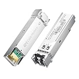
- High-Performance LC SFP Module: Connect a network switch, server, NIC, media converter with an SFP port to a Gigabit fiber network using this 1000BASE-SX SFP transceiver. The multimode SFP module with LC interface provides standards-based 1000BASE-SX Gigabit Ethernet over duplex LC multimode fiber for reliable short-reach links.
- Universal MSA Compatibility: This SFP LC multimode transceiver works with MSA-compliant equipment from Cisco, HPE Aruba, Ubiquiti, MikroTik, Fortinet, Meraki, Huawei, Netgear, TP-Link, D-Link, and Supermicro. The 1G multimode SFP module supports DDM/DOM (SFF-8472) for flexible deployment and seamless integration. (Not for proprietary vendor-locked SFP ports.)
- Energy-Efficient & Hot-Pluggable: Designed for low power consumption (<0.5 W) and minimal EMI emissions, this SFP fiber module ensures reliable, interference-free operation. Its hot-pluggable design with built-in ESD protection allows safe installation and removal in data center or enterprise network environments.
- Reliable Gigabit Transmission: This SFP multimode LC module supports up to 1.25 Gbps line rate at an 850 nm (VCSEL). Reach up to 550m on 50/125µm (OM2/OM3/OM4) and up to 275m on 62.5/125µm (OM1) over 1000BASE-SX. Fully compliant with IEEE 802.3z 1000BASE-SX, SFP MSA (INF-8074i).
- Convenient 2-Pack: Each package includes two LC fiber SFP modules for scalable deployment and maintenance. Perfect for equipping multiple switches or keeping a spare 1G SFP LC module for quick replacement in data rooms or field operations.
As lane rates rise, electrical routing becomes more demanding. Longer traces, connectors and other channel elements contribute loss and can complicate signal integrity; designers may need to adjust the route, use compensation, or bring the conversion point closer to the ASIC. Optical transmission changes the medium for the longer part of the link, but it does not make the electrical path to the optical engine disappear.
CPO moves optical components next to the IC on the same substrate, reducing that electrical segment. It still requires electrical-to-optical conversion, optical engines, fiber routing and precise coupling between fiber and photonic components. Corning highlights fiber alignment and harnessing as continuing integration concerns; Molex also points to thermal isolation, testing and assembly as design considerations. These are supplier-described engineering issues, not an independent comparison of how often different designs fail or what they cost.
How the main architectures compare
| Architecture | Where it fits | What it changes | Questions to resolve |
|---|---|---|---|
| PCB electrical channel | Between board-mounted components, packages and ports | Keeps the link electrical; channel length, connectors and signal conditioning shape its limits. | What are the channel loss and crosstalk? What lane rate, route length, stack-up and equalization or retiming are supported? |
| Short-reach copper cable or AEC | Nearby equipment, often within a rack | Moves part of the connection off the board while remaining electrical. | Does the cable support the required reach and host/port combination? Can the design accommodate its power, airflow and cable congestion? |
| Near-ASIC or co-packaged copper (CPC) | At or close to an ASIC or package | Can shorten the electrical route through the board; introduces package-adjacent assembly and serviceability choices. | How are the assembly, rework, substrate protection and upgrade path handled? |
| Pluggable optics | Equipment faceplate and links that need fiber reach | Places conversion in a module at the port; fiber carries the longer optical segment. | Do module, connector, fiber topology and endpoints match? Are power, cooling and maintenance requirements acceptable? |
| CPO or near-package optics | Optical engine adjacent to or co-packaged with compute or switching silicon | Shortens the electrical path between the IC and optics while retaining optical conversion and fiber integration. | Can the design manage fiber coupling, thermal placement, testing, yield and repair? |
| Chiplet or die-to-die interface | Inside a multi-die package | Connects dies over a common-package medium; it is not a rack-network link. | What package medium, bandwidth density, latency, energy-per-bit target, interoperability and manufacturing test are required? |
These architectures are not interchangeable solely because they carry data. A chiplet interface, a board channel and a rack link have different endpoints and physical media; comparing them requires a defined system boundary.
The Tool Desk
Outbyte PC Repair FREEClear out junk files and repair common Windows errorsFree Scan →Outbyte Driver Updater FREEFix the driver behind crashes, sound loss and screen glitchesFind Drivers →Rank #2

- 1000Base-LX/LH SFP: Gigabit Single Mode SFP Module support 1.25 Gb/s data rates, 1310nm wavelength, SMF; Duplex Dual LC interface connected to Single-mode (OS1/OS2/OS3) LC/UPC fiber cable, up to 20km (12.4 mile); 2 Pack
- Wide Compatibility: Perfect for Cisco GLC-LH-SMD, Meraki, Ubiquit,UniFi, Mikrotik, Intel, Fortinet, Netgear, D-Link, TP-Link and Other Open Equipment
- Easy to Use: 1G SFP transceiver with advanced DDM function to monitor real-time parameter and state on fiber links; It supports hot-swappable, plug and play; SFP MSA Compliant, IEEE 802.3z compliant
- Low Power Consumption: 1Gb SFP transceiver designed for energy efficiency, less than 1.05watt Power Consumption; Low EMI and advanced ESD protection
- Friendly Service: Each sfp module is individually done test before packing; We provide 24/7 Customer Service, 30 Days Free-returned, 3 Year Free Warranty and Lifetime Technology Support
What PCIe 6.0 and 7.0 rates do—and do not—tell you
PCI-SIG lists PCIe 6.0 at 64.0 GT/s raw and up to 256.0 GB/s over a x16 link. The specification uses PAM4 signaling and Flit mode with FEC/CRC, and its technology page describes backward compatibility. Those are interface-standard characteristics, not a promise that every board route can meet a target reach without retimers, equalization or other design measures.
PCI-SIG says PCIe 7.0 version 1.0 was released to members on June 11, 2025, at 128.0 GT/s. The specification’s stated goals include optical interconnection between compliant silicon and extended reach across racks and pods. A standards release and its goals do not establish that optical PCIe deployments are generally available or that a particular product supports them.
For data-centre Ethernet, the Ethernet Alliance’s 2026 roadmap includes 800G and 1.6T interfaces and discusses CPO, CPC, and linear or retimed pluggable optics (LPO/LRO) in the context of power efficiency. A roadmap indicates industry direction; it is not an independent deployed-performance benchmark or a universal design recommendation.
Rank #3

- Transmits using a 1310nm wavelength and supports 1080p, 720p, NTSC, and PAL video resolutions
- Bidirectional TxRx Tranceivers where Tx stands for Transmitter and Rx for Receiver
- Compatible with a wide range of optical fiber video equipment, such as Blackmagic Mini Converter Optical Fiber 12G, Blackmagic Studio Camera (4K), ATEM Talkback Converter 4K, ATEM Studio Converter, ShieldRock Optical-Fiber Extenders
DR4 or FR4: what is the difference?
DR4 and FR4 describe different optical configurations, not two labels that can be assumed to mate directly. NVIDIA’s LinkX product information gives these examples: DR4 uses four parallel channels over eight fibers with MPO-12/APC connectors, while FR4 multiplexes four wavelengths over a fiber pair with LC connectors. NVIDIA explicitly says DR4 and FR4 cannot be directly linked to each other.
| Example configuration | Fiber and connector arrangement | Published reach example |
|---|---|---|
| DR4 | Four parallel channels over eight fibers; MPO-12/APC | Up to 500 m in NVIDIA’s stated single-mode product example |
| FR4 | Four wavelengths multiplexed over a fiber pair; LC | Up to 2 km in NVIDIA’s stated product example |
Those distances are product-specific examples from NVIDIA’s LinkX page, not general maximum reaches for every DR4 or FR4 implementation. Check the module specifications, fiber type, connector, link budget and both endpoints. A matching label alone does not guarantee compatibility.
When is copper the better fit, and when should you consider optics?
There is no universal distance or data rate at which copper must give way to optics. The sources establish useful examples, but not a controlled, cross-architecture break-even point for cost, power per bit, reliability or thermal load.
Rank #4

- OREI 1G SFP Fiber Optical Transceiver Module - OREI 1000BASE SFP optical transceiver supports stable 1Gbps Gigabit Ethernet transmission over multimode fiber using an 850nm wavelength
- Multimode Fiber SFP up to 550m - Designed for short-range fiber optic networks, this multimode SFP module delivers reliable performance up to 550 meters for LAN, enterprise, and AV-over-IP setups
- Standard SFP Form Factor – Hot Swappable - Fully compliant with SFP MSA standards, allowing plug-and-play installation and hot swapping in compatible fiber switches, routers, and media converters
- LC Duplex Fiber Connector - Equipped with an LC duplex optical interface supporting separate transmit (TX) and receive (RX) paths for secure and low-loss fiber connections
- Wide Compatibility & Certified Design - Compatible with SFP-enabled network switches, routers, firewalls, and fiber media converters; CE, FCC, RoHS, and REACH compliant for professional use
Keep the link electrical when the complete channel supports it
For short board routes or nearby equipment, PCB routing, short copper cables and AECs may fit the system without adding an optical conversion point. NVIDIA lists LACC/AEC copper examples up to 2.5–3 m for specified XDR 2x800G and 1.6T Ethernet deployments; Marvell describes AECs for short-reach, within-rack links. Neither example is a general reach guarantee for other products or configurations.
Near-ASIC CPC is another option when reducing board routing is valuable but a copper connection remains suitable. Molex presents CPC as a serviceable near-ASIC approach, while Marvell describes it as extending copper closer to the package or cable. Treat those as supplier descriptions: the design still needs to account for assembly, rework, density and how a component can be replaced or upgraded.
Use pluggable optics when the system needs a fiber link
Pluggable optics put the transceiver at the equipment faceplate and use fiber for the link beyond it. They can suit connections whose reach or electrical-channel constraints call for optical transmission, but the decision depends on the exact module and link budget—not a generic distance rule. Fiber count, connector, wavelength arrangement, module compatibility, power and cooling all matter.
Best Value

- What You Get: 2pcs Gigabit Multi-Mode Ethernet SFP Slot media converters; 2pcs SFP BiDi LC Dual Multi-Mode transceiver; 2pcs AC/DC Power Supply; 1 x User’s Manual. Support wide power supply voltage (100V-240V), Power Supply: 5V-1A, UL Certified.
- Fiber Optical Port: 1.25Gbps SFP port, connecting the BiDi Multi-Mode LC Dual transceivers up to 550M(2 SFP LX Transceiver included); Fiber Type: MMF, Cable Type: UTP/STP Cat.5e for 100 meters.
- RJ45 Port: 10M/100M/1000M Auto-negotiation, full Duplex or half Duplex, Auto-negotiation, Supports MDI/MDIX auto-crossover, Complies with IEEE 802.3/802.3u/802.3z/802.3ab.
- Plug & Play: Simply plug in optical port and RJ45 port, and it will work immediatelly. Status LED's for TX, FX LINK/ACT, POWER, FDX to easily monitor network status. Supports jumbo frame size 9K bytes; Supports working temperature range from 0°C to 60°C.
- 【100% Money Guarantee】15 years OEM factory competency, Most efficient technical support with superb processing technology.★Our committed to provide the best product and services to every customer.
Evaluate CPO when the electrical path to the optics is the design problem
CPO can reduce the length of high-speed electrical routing between an ASIC and optical engines by placing the optics close to the IC. That integration exchanges some board-channel challenges for package, fiber-coupling, thermal, test and serviceability challenges. The evidence here does not establish a universal cost, power or reliability advantage over pluggable optics or other architectures.
Independent reader supportYour contribution helps us test, update, and keep practical guides available for everyone.A practical way to select an architecture
- Define endpoints and link purpose. State whether the connection is die-to-die, board-level, within a rack, between systems or part of a larger network. Specify the protocol and the required topology.
- Set the actual channel requirements. Record the distance, lane rate, bandwidth, connector transitions and operating conditions. Distinguish a standard’s raw signaling rate from the bandwidth and channel performance required in the product.
- Model the electrical path. Account for PCB routing, connectors, channel loss and crosstalk, and the equalization or retiming required by the design. Use channel simulations and component specifications for the intended implementation.
- Compare physical options at the right integration point. Consider board routing, short copper or AEC, CPC, pluggable optics and CPO only where their endpoints and reach make them relevant. For an in-package die-to-die link, assess a package-level interface such as the one addressed by OCP OpenHBI rather than treating it as a rack link.
- Check compatibility end to end. Confirm protocol, module or cable support, connector, fiber arrangement, endpoints and the complete link budget. Do not infer compatibility from a product-family label alone.
- Include operational and manufacturing constraints. Compare port power and cooling, cable routing, density, test access, assembly and rework, repairability and the intended upgrade path.
- Validate against the target system. Use supplier data sheets and design-specific simulations, then validate the actual channel and thermal design. The available public material does not provide a universal numeric crossover point or an independent head-to-head comparison across these architectures.
Keep package links separate from rack links
OCP’s OpenHBI specification defines a high-performance die-to-die or chiplet-to-chiplet interconnect over a silicon interposer or equivalent technology in a common package. It addresses concerns such as interoperability, manufacturability and testability. That is a package-level problem: its medium and design goals should not be confused with fiber or copper links that connect equipment across a rack or data-centre network.
Quick Recap
Product prices and availability are accurate as of the date/time indicated and are subject to change. Any price and availability information displayed on Amazon at the time of purchase will apply.
Recommended Free Tools

